Attitude Indicator
The attitude indicator, or artificial horizon, is the gyroscopic instrument that shows the aeroplane's pitch and bank against a horizon held level by a vertical gyro. It is the only instrument that presents attitude directly and is the centre of the instrument scan in cloud or at night.
The attitude indicator (AI), also called the artificial horizon or gyro horizon, shows the aeroplane's pitch and bank against a horizon kept level by a gyroscope. In cloud, at night or over a featureless sea it replaces the natural horizon, and it is the one instrument that presents attitude directly and without lag. It sits at the top centre of the basic T, with the airspeed indicator on its left, the altimeter on its right and the heading indicator below.
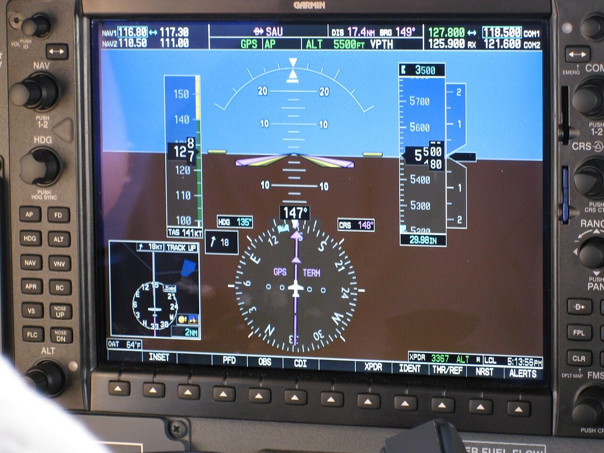
In a light aeroplane the attitude indicator is usually a self-contained, vacuum-driven gyro instrument. In a glass cockpit the same picture is drawn on the primary flight display from an attitude and heading reference system (AHRS) or, in an airliner, from the inertial reference system, with an independent standby instrument alongside. The principles, and most of the exam questions, still start with the mechanical vertical gyro.
Attitude indicator overview
The display has two parts. A miniature aircraft, the gull-wing symbol, is fixed to the case and therefore to the aeroplane. Behind it, a horizon bar or horizon card is linked to the gyro and stays parallel to the real horizon. When the nose rises the symbol rises above the bar; when the aeroplane banks right the bar tilts so that the symbol's right wing lies below it. Pitch is read in degrees on a ladder of lines above and below the horizon.
A bank angle indicator completes the display: a pointer moving against a scale of bank marks. On the Boeing 737 primary flight display and the A320's integrated standby instrument the scale is marked at 0°, 10°, 20°, 30°, 45° and 60°. On some electromechanical instruments the pointer turns with the horizon card, so it may sit on the side of the scale opposite the lower wing; the symbol against the bar is the reliable reading.
Some instruments, mostly American, have a knob that moves the miniature aircraft up or down, so that the symbol can be set against the horizon for the normal level-flight attitude. It is set before flight and left alone in cloud, where a misadjusted datum would give a false pitch picture on the approach.
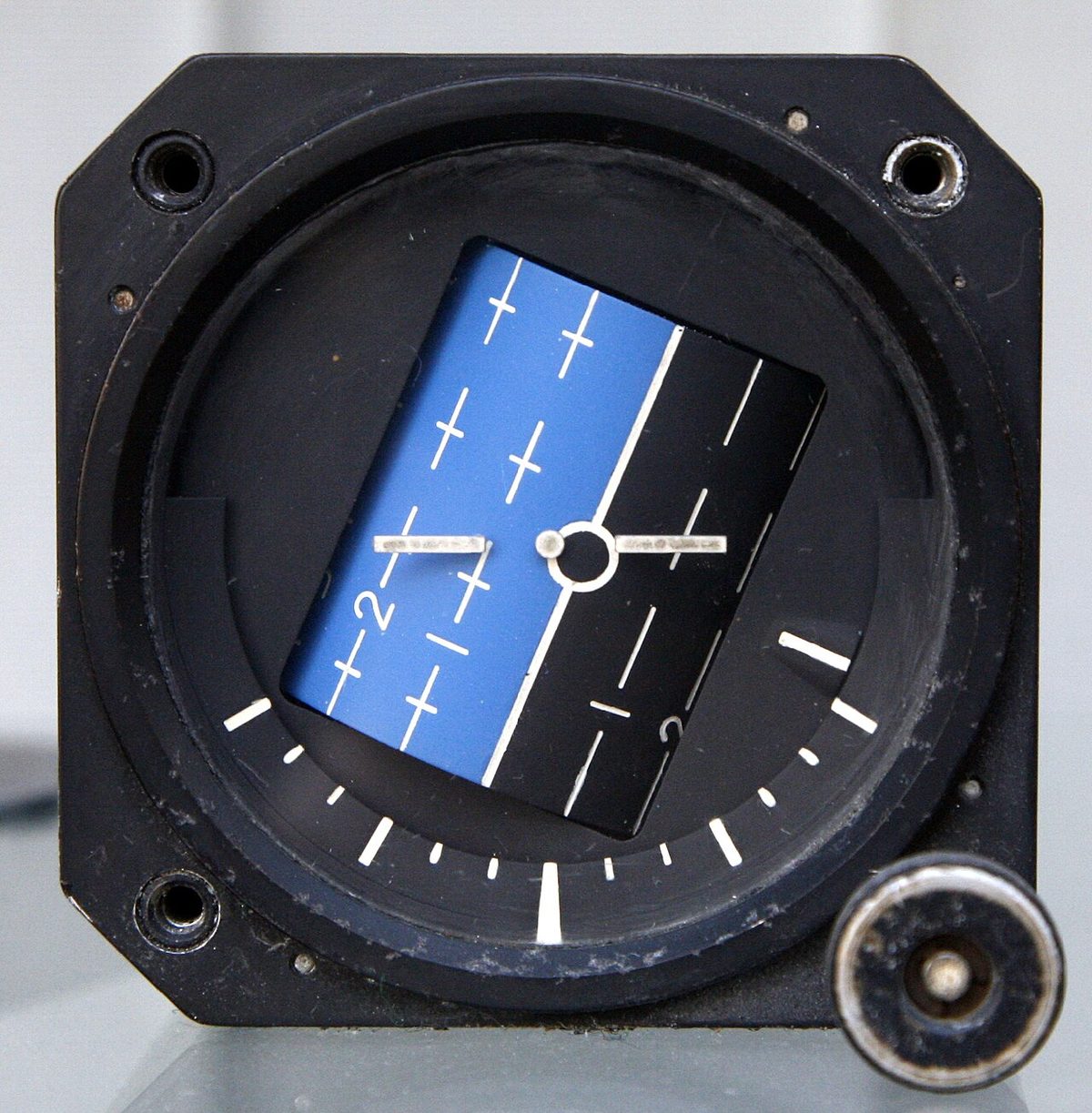
Exam tip: read the fixed symbol against the moving horizon. Right wing below the bar at the 20° mark, symbol above the bar: 20° of right bank, nose up. At 130 kt TAS that bank is about rate one, since the rule of thumb gives 130 ÷ 10 + 7 = 20°.
Vertical gyro construction
The gyro of an attitude indicator is an earth gyro: its spin axis is tied to the local vertical by gravity, so its rotor turns in the horizontal plane. It is a displacement gyro with two gimbals, giving it freedom in pitch and roll relative to the case; its rigidity holds the rotor level while the aeroplane moves around it (see gyroscopic principles). A guide pin connects the gyro to the horizon bar.

Rigidity rises with rotor speed. Exam texts quote about 15,000 rpm for an air-driven rotor and about 22,500 rpm for an electric one. Electric gyros are heavier and more expensive but spin faster, hold their speed more precisely and are more rigid.
Every gimbal system has limits. Older instruments topple beyond about 60° of pitch or 110° of bank; the gimbals then reach their stops and the horizon moves violently and erratically. Modern instruments typically allow about 85° of pitch and complete freedom in roll. An air-driven instrument that has toppled takes typically 10 to 15 minutes to re-erect by itself, because its erection forces are small. If a caging device is fitted, the gyro is uncaged at least 5 minutes before take-off so that the rotor can run up and the axis settle on the vertical.
A vertical gyro unit (VGU) does the same job remotely. It is a vertical gyro mounted away from the panel whose electrical outputs feed attitude displays, flight director and autopilot, so that several indicators can share one sensor.
Erection systems and pendulous vanes
Bearing friction, imbalance and the Earth's rotation all make a free gyro wander, so an attitude indicator needs a gyro erection system that keeps pushing the spin axis back to the vertical. It works through precession: a small force is applied, and the gyro responds 90° further round in the direction of rotation.
Pendulous vanes erect an air-driven gyro. The air that has spun the rotor leaves through four slots at the bottom of the rotor housing, each half covered by a vane hanging under gravity. With the axis vertical the four jets are equal and cancel. If the axis tilts, the vanes stay hanging vertically: one opens its slot fully while the opposite one closes, and the unbalanced jet's reaction, precessed through 90°, drives the axis back to the vertical. The rotor housing is also made slightly bottom-heavy, which shortens the initial erection time.
An electric instrument uses a mercury levelling switch for pitch and another for roll at the base of the rotor, each with a torque motor. When the axis tilts, the mercury runs off centre, closes a circuit and the torque motor applies a correcting torque, again precessed into the right direction. Because the switches and motors keep the axis vertical, the housing can be less bottom-heavy.
Erection cut-out and fast erection
Any gravity-sensing device is fooled by acceleration, so electric instruments disconnect erection when it would do harm. Pitch and roll cut-out switches open the torque motor circuits: in the figures exam texts use, the pitch cut-out operates at a longitudinal acceleration of 0.18 g or more, and the roll cut-out at about 10° of bank. Erection resumes once the condition has passed.
A fast erection system lets the pilot raise the torque motor voltage, typically by pressing a knob on the face. The erection rate rises from a normal figure of about 4° per minute to about 120° per minute. It is used after start-up and to recover a toppled gyro, and only in straight, level, unaccelerated flight; in a turn or an acceleration it would align the gyro quickly with a false vertical.
Exam tip: the erection rate is deliberately slow. That is what keeps short manoeuvres from dragging the gyro off the vertical, and it is also why errors that do build up during long turns or accelerations take minutes to wash out.
Vacuum and air-driven gyros
In the classic light-aeroplane installation an engine-driven vacuum pump draws air through a filter and through the gyro instruments, where jets strike buckets cut in the rotors and spin them. The attitude and heading indicators are air-driven in this way; the turn coordinator is electric, so that one failure cannot remove every gyro instrument.
A suction gauge shows the pressure difference that drives the gyros. FAA material gives a typical normal range of 4.5 to 5.5 inHg. Below the manufacturer's range the rotors slow down and lose rigidity. A low reading points to a failing pump, a leak or a clogged filter; at high altitude an engine-driven pump may also struggle, because there is less pressure difference to work with.
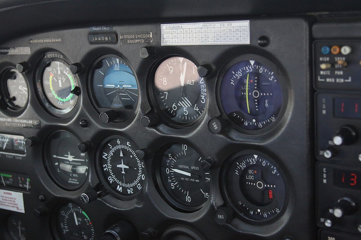
A vacuum failure is insidious. The gyros run down over several minutes and the attitude indicator drifts into a slow, plausible bank or pitch, often without any flag. A pilot who follows it banks the aeroplane while the turn coordinator shows a turn and the altimeter starts to unwind. A tumbled attitude indicator with normal suction points to the instrument itself; low suction implicates the pump, and the heading indicator will follow.
Warning: after a vacuum failure in cloud, cover the attitude and heading indicators and fly partial panel: turn coordinator for bank, compass for heading, and the altimeter, vertical speed and airspeed indicators for pitch.
The rules decide when an attitude indicator is required. For non-commercial flights under Part-NCO in Europe, attitude, stabilised heading and turn and slip indications become mandatory at night and under IFR; FAA 14 CFR 91.205(d) requires a gyroscopic pitch and bank indicator for IFR, so an aeroplane without an MEL whose attitude indicator has failed may depart only under VFR, with the instrument deactivated and placarded.
Acceleration and turning errors
The erection system cannot tell gravity from acceleration. When the aeroplane accelerates, it senses a false vertical tilted backwards and starts to precess the gyro towards it.
On an air-driven instrument whose rotor turns anticlockwise seen from above, the convention of British exam texts, the take-off run or a go-around at full power produces a false nose-up and a false right-wing-down indication: an apparent climbing turn to the right. The lagging pendulous vanes cause the pitch error; the inertia of the bottom-heavy rotor housing, precessed through 90°, causes the bank error. Deceleration gives the opposite, a false nose-down and left-wing-low picture.
Electric instruments suffer much less. Their faster rotors precess more slowly under the same force, their housings are less bottom-heavy and their cut-outs stop false erection.
Turning errors have the same cause. In a sustained turn the vanes or switches sense the resultant of gravity and centripetal acceleration and erect the gyro towards that false vertical. During the turn an uncompensated air-driven instrument shows a small false climb and a bank error that varies round the circle; after a full 360° the errors cancel. After a 180° turn, small pitch and bank errors remain on rolling out and wash out at the slow erection rate. Some instruments reduce the errors with a small built-in tilt of the rotor axis, about 2°, which is exact only for one rate of turn and TAS.
| Condition | Air-driven indication (anticlockwise rotor) | Effect on electric instrument |
|---|---|---|
| Acceleration | False nose-up, false right bank | Much smaller; pitch cut-out |
| Deceleration | False nose-down, false left bank | Much smaller |
| Sustained turn | Pitch and bank errors, cancel after 360° | Much smaller; roll cut-out |
| Rolling out after 180° | Small residual pitch and bank errors | Smaller |
The danger is at low level at night. The false climb shown after a go-around or a take-off towards a dark sea coincides with the somatogravic illusion, the feeling of a steep pitch-up caused by the same acceleration acting on the inner ear (see spatial disorientation). Lowering the nose to correct either is dangerous; the altimeter and vertical speed indicator settle the question.
Electric vertical gyros and AHRS
In most modern aircraft attitude comes from an electronic reference. An attitude and heading reference system (AHRS) supplies attitude to the flight displays and to systems such as the autopilot and weather radar, and heading from a magnetometer; unlike an inertial reference unit, it does not compute position. If it fails, the attitude and heading on the primary flight display are replaced by red crosses, while airspeed, altitude and vertical speed, which come from the air data computer, remain. The pilot then flies on the standby attitude indicator and the magnetic compass.
In airliners the inertial reference system is the attitude source. On the Boeing 737 the IRSs are the only source of attitude and heading apart from the standby attitude indicator and standby compass; on the A320 the IR part of each ADIRU supplies attitude with heading, track and position (see inertial reference system alignment and modes).
The standby attitude indicator must work independently of the primary displays. European operating rules for commercial air transport require it to keep working reliably for at least 30 minutes after a total failure of the normal electrical generating system. On 737 variants with an electromechanical standby, it is powered from the battery bus; its gyro reaches operating speed about 60 seconds after power is applied and needs three minutes to reach full accuracy. Glass-cockpit light aircraft often have a standby unit with its own battery, tested before flight.
Checks and use in flight
Before flight the horizon bar should be level, with the pitch indication correct for the aeroplane's ground attitude. During taxi turns the attitude indicator should stay level while the turn coordinator and heading indicator show the turn. An instrument that is slow to erect or shows a bank while taxiing straight is failing, and an IFR departure in low cloud is not an option.
In flight the attitude indicator is the control instrument and the hub of the scan: each glance at a performance instrument starts and ends there. It is not infallible. If the altimeter and vertical speed indicator show a descent while the attitude indicator shows level flight, the aeroplane is descending; a small pitch correction, retrim and a further cross-check follow, and a larger disagreement is treated as a possible instrument failure.
Frequently asked questions
How do you read an attitude indicator?
The miniature aircraft symbol is fixed to the case and so moves with the aeroplane, while the horizon bar is held level by the gyro. Read the symbol against the bar: a wing below the bar means a bank to that side, and the symbol above the bar means nose up. The bank scale and pointer give the angle of bank, the pitch ladder the pitch attitude in degrees.
Why does the attitude indicator show a climb during the take-off run?
The erection system senses the vertical with gravity-sensitive devices, pendulous vanes on air-driven instruments and mercury switches on electric ones. A strong forward acceleration swings them backwards as if the aircraft had pitched up, so they precess the gyro towards a false vertical. An air-driven instrument therefore shows a false nose-up, and the inertia of its bottom-heavy rotor housing adds a slight false right bank; deceleration gives the opposite. Cross-check with the altimeter and vertical speed.
What happens to the attitude indicator when the vacuum pump fails?
The rotor slows down over several minutes and loses rigidity, so the instrument drifts slowly into a false but believable bank or pitch, often without any warning flag. The heading indicator decays in the same way. The suction gauge, normally 4.5 to 5.5 inHg in a typical light aeroplane, gives the warning. Cover the failed instruments and fly partial panel on the electric turn coordinator.
What is fast erection on an attitude indicator?
Fast erection is a push-button or knob on electric attitude indicators that raises the voltage to the erection torque motors, increasing the erection rate from a few degrees per minute to over a hundred. It re-erects the gyro after start-up or after it has toppled. It must be used only in straight, level, unaccelerated flight, otherwise the gyro is erected quickly to a false vertical.
What is an AHRS?
An attitude and heading reference system is an electronic unit that supplies pitch, roll and heading to the flight displays, autopilot and other systems, with a magnetometer for heading. It replaces the vacuum gyros of a glass cockpit. Unlike an inertial reference system it does not compute position. If it fails, attitude and heading are lost but air data is not, and the pilot flies on the standby attitude indicator and compass.
Test yourself on Attitude Indicator
The v1prep banks cover this topic in Instrumentation (022), with a worked explanation for every answer. EASA ATPL, PPL, IR and CPL, the FAA written tests and A320/B737 type ratings.
Start practising →Sources and further reading
- FAA Instrument Flying Handbook (FAA-H-8083-15B), Chapter 5, Flight Instruments
- FAA Pilot's Handbook of Aeronautical Knowledge (FAA-H-8083-25), Chapter 8, Flight Instruments (gyroscopic instruments)
- FAA Aeronautical Information Manual, Chapter 1 Section 1 (1-1-15, IRU, INS and AHRS)
- 14 CFR 91.205, Instrument and equipment requirements (IFR instruments)
- EASA Easy Access Rules for Air Operations (Regulation (EU) No 965/2012), instruments and equipment (NCO.IDE, CAT.IDE)
- EASA, Explanatory Note to ED Decision 2018/001/R, Part-FCL theoretical knowledge learning objectives (022 Instrumentation)
Library articles are written for study and exam preparation. They do not replace your aircraft's approved documentation, your operator's procedures or the regulations themselves.