AC Electrical Theory
Alternating current is an electric current that reverses its direction periodically, normally following a sine wave. Transport aircraft generate it as three-phase 115/200 V at a constant 400 Hz, and it is described by RMS values, the phase angle between voltage and current, and the relationship between true, reactive and apparent power.
Alternating current (AC) is current that flows back and forth about a mean position, its polarity reversing continuously, instead of flowing one way as direct current does. Large transport aircraft generate their primary electrical power as AC: the A320's power system, for example, is a three-phase 115/200 V, 400 Hz constant-frequency AC network with a separate 28 V DC system fed from it.
AC is preferred for the main supply of large aircraft for several reasons. AC machines have no commutator, so they are simpler, lighter for their output and free of brush arcing at altitude; transformers change AC voltages with almost no loss, and DC is easily obtained from AC through transformer rectifier units; three-phase AC motors are simple and efficient; and a higher system voltage means a lower current and lighter cables for the same power. Understanding the system requires a handful of ideas that DC does not need: RMS values, phase, power factor and three-phase connections.
Alternating current basics
A coil rotating in a magnetic field has its sides cut the flux first in one direction and then in the other, so the induced EMF alternates naturally. Plotted against time it is a sine wave: zero, rising to a positive peak, back through zero to a negative peak, and back to zero. That is one cycle. The number of cycles per second is the frequency, in hertz (Hz), and the time for one cycle is the period, 1 divided by the frequency: at 400 Hz, 2.5 milliseconds.
The frequency of an AC generator depends on its speed and its number of magnetic poles, which always come in north-south pairs, each pair producing one cycle per revolution:
frequency (Hz) = (number of poles ÷ 2) × (rpm ÷ 60)
An 8-pole generator turning at 6,000 rpm gives 4 × 100 = 400 Hz. Frequency is tied to speed, so a constant-frequency supply needs a generator turning at constant speed whatever the engine is doing. That is the job of the constant speed drive, packaged with the generator as the integrated drive generator, or IDG (see AC generators, CSD and IDG). A frequency-wild alternator, driven directly by the engine, has a frequency that varies with engine speed; it serves loads that do not care about frequency, such as resistive heater mats.
RMS values and frequency
A sine wave is described by its peak value, its peak-to-peak value (twice the peak) and, most usefully, its root mean square (RMS) value. RMS is the effective value: the steady DC voltage or current that would produce the same heating in a resistor. For a sine wave:
- RMS = peak × 0.707 (peak ÷ √2)
- peak = RMS × 1.414 (RMS × √2)
AC voltmeters and ammeters are calibrated in RMS, and any AC voltage quoted without qualification is an RMS value. The aircraft's 115 V supply therefore has a peak of about 115 × 1.414 ≈ 163 V, and its 200 V line voltage a peak of about 283 V. The 0.707 factor applies only to sine waves: a square wave's RMS value equals its peak, and a triangular wave's is its peak divided by √3.
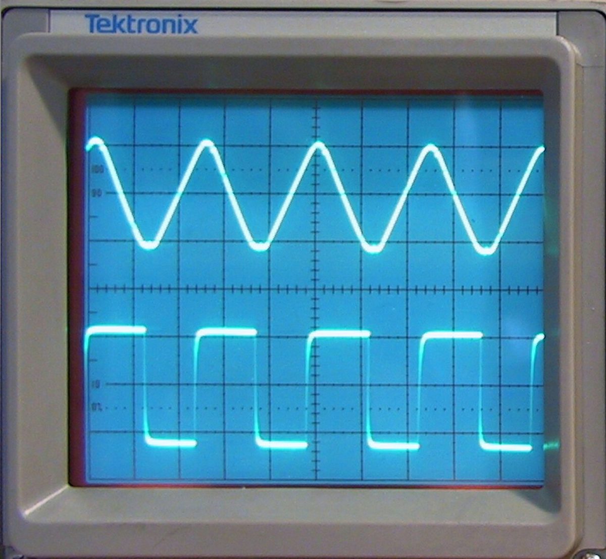
The supply is held within tight limits of voltage and frequency, and the generator control units trip a generator whose output strays outside them. The A320 shows the kind of values involved: its ECAM electrical page turns a generator's frequency amber below 390 Hz or above 410 Hz, and the emergency generator's and static inverter's voltage amber below 110 V or above 120 V (see generator control, protection and paralleling).
Phase angle and the CIVIL rule
Voltage and current in an AC circuit are both sine waves at the same frequency, but they do not necessarily reach their peaks together. The phase angle (φ) is the angle, in degrees of a 360° cycle, by which the current leads or lags the voltage.
- In a purely resistive circuit, voltage and current are in phase: they pass through zero and reach their peaks together, and φ = 0°.
- In a purely inductive circuit, current lags voltage by 90°. A changing current in a coil induces a back EMF that opposes the change (Lenz's law), so the current cannot rise as fast as the voltage and peaks a quarter-cycle later.
- In a purely capacitive circuit, current leads voltage by 90°. Current must flow first to charge the plates before the voltage between them can rise.
The CIVIL mnemonic gathers this up: in a Capacitor, I leads V; V leads I in an inductor (L). Real loads contain resistance and reactance together and have phase angles between 0° and 90°. The opposition that an inductor or capacitor offers to AC is called reactance, and the combined opposition of resistance and reactance is the circuit's impedance. Motors and transformers are coils, so they are inductive loads, and their current lags the voltage.
Exam tip: "voltage leads current" means an inductive circuit; "current leads voltage" a capacitive one. CIVIL answers both in one word.
True, reactive and apparent power
When voltage and current are out of phase, simply multiplying them no longer gives the power actually used. Three quantities are distinguished:
| Quantity | Symbol and unit | Single-phase formula | Meaning |
|---|---|---|---|
| True power (real, active) | P, watts (W, kW) | P = V × I × cos φ | Power actually converted into heat, light or mechanical work |
| Reactive power | Q, volt-amperes reactive (VAR, kVAR) | Q = V × I × sin φ | Power flowing back and forth between the source and the inductors or capacitors, stored in their fields and returned, never consumed |
| Apparent power | S, volt-amperes (VA, kVA) | S = V × I | Total power the source must supply, including the reactive part |
V and I are RMS values. Because cos² φ + sin² φ = 1, the three form a right-angled power triangle: S² = P² + Q². In a pure resistance cos φ = 1, so true power equals apparent power; in a pure inductance or capacitance cos φ = 0, and no true power is used at all even though current flows.
Reactive power does no useful work, but its current is real. It flows through the generator windings and the cables and heats them, which is why it matters.
Power factor and kVA ratings
The power factor (PF) is the ratio of true power to apparent power, which equals the cosine of the phase angle:
power factor = P ÷ S = cos φ
It runs from 0 to 1. A resistive load has a power factor of 1, the most efficient case. An inductive load has a lagging power factor, a capacitive one a leading power factor. Aircraft systems aim for a power factor close to 1.
Generators are rated in kilovolt-amperes (kVA), apparent power, not in kilowatts. The windings heat with the full current they carry, whatever its phase, so the machine's capability is fixed by volts times amps. The true power it delivers depends on the power factor of the loads, which changes through the flight.
For example, a 90 kVA generator supplying loads with a power factor of 0.8 delivers 90 × 0.8 = 72 kW of true power, and the remaining √(90² − 72²) = 54 kVAR is reactive. Aircraft ratings are given in kVA for the same reason:
| Source | Rating |
|---|---|
| A320 engine-driven generator (IDG), each | 90 kVA, three-phase 115/200 V 400 Hz |
| A320 APU generator | The same as each engine generator |
| A320 emergency generator | 5 kVA, three-phase 115/200 V 400 Hz |
| A320 static inverter | 1 kVA, single-phase 115 V 400 Hz |
| Embraer E190 E1 IDG, each | 40 kVA |
| Embraer E190-E2 IDG, each | 50 kVA; APU generator 40 kVA |
Exam tip: kW = kVA × power factor. A question that gives a generator's kVA rating and a power factor is asking for its true power.
Three-phase AC and phase sequence
Three-phase AC is generated by three separate windings spaced around the alternator's stator, so that their three sine waves are 120° apart: each phase reaches its peak a third of a cycle after the one before. Three-phase supply feeds large loads evenly, and passed through the stator windings of a motor it produces a rotating magnetic field, which is what makes three-phase motors so simple (see transformers, converters and AC motors).
The phase sequence is the order in which the three phases reach their peaks, for example A, B, C (or red, yellow, blue). Swapping any two phase connections reverses the sequence, and with it the direction in which a three-phase motor turns. The sequence therefore matters:
- two alternators can be paralleled only if their voltage, frequency, phase and phase sequence all match;
- aircraft external power circuits reject a ground supply whose phase sequence is wrong, since it would run motors backwards.
Star connection, line and phase voltage
The three windings of an aircraft alternator are joined in a star connection (Y). One end of each winding is connected to a common neutral point, normally connected to the airframe, and the other three ends are the lines. Two voltages are then available:
- the phase voltage, between any line and the neutral: 115 V;
- the line voltage, between any two lines: 200 V.
Because the two phases measured are 120° apart, the line voltage is their vector difference, √3 (about 1.732) times the phase voltage: 1.732 × 115 ≈ 200 V. The line current equals the phase current, since each line carries the current of one winding. The neutral carries any out-of-balance current when the three phases are unequally loaded. Single-phase loads are connected between one line and the neutral at 115 V; lower voltages, such as the 26 V AC used by some instruments, are taken through transformers.
The total power of a balanced three-phase supply is three times that of one phase:
P = 3 × V(phase) × I(phase) × cos φ = √3 × V(line) × I(line) × cos φ
A worked example: a 90 kVA generator gives 30 kVA per phase, so at 115 V each phase can carry 30,000 ÷ 115 ≈ 261 A at full rating.
Why aircraft use 400 Hz
The standard transport-aircraft supply, three-phase 115 V 400 Hz AC power, often written as constant-frequency AC power (115/200 V 400 Hz), is chosen for weight. The EMF induced in a transformer winding is given by E = 4.44 × f × N × B × A, where f is the frequency, N the number of turns, B the peak flux density and A the area of the iron core. For a given voltage, turns and flux density, the core area needed is inversely proportional to frequency: at 400 Hz it is in principle an eighth of what 50 Hz would need. The 400 Hz aircraft AC supply therefore allows much smaller and lighter transformers, motors and inductors.
The price is paid over distance: at high frequency, losses rise when power is transmitted over long lines. Aircraft cable runs are short, so it does not matter. Holding the frequency at 400 Hz needs a constant speed drive, or a variable speed constant frequency (VSCF) system that converts frequency-wild output into constant-frequency AC electronically. The DC buses are then fed from the AC system through transformer rectifier units (see electrical power distribution).
Frequently asked questions
Why do aircraft use 400 Hz instead of 50 or 60 Hz?
For a given voltage, the iron core a transformer or motor needs becomes smaller as the frequency rises, because the induced voltage is proportional to frequency, turns, flux density and core area. At 400 Hz, transformers, motors and inductors are much smaller and lighter than at 50 or 60 Hz, a large saving on an aircraft. The penalty, higher losses when power is sent over long distances, does not matter over the short cable runs in an aircraft.
What does 115/200 V mean on an aircraft AC system?
It describes a three-phase star-connected supply. 115 V is the phase voltage, measured between any one phase and the neutral; 200 V is the line voltage, measured between any two phases. In a star connection the line voltage is the square root of 3, about 1.732, times the phase voltage, and 1.732 times 115 V gives about 200 V. Both are RMS values at a constant 400 Hz.
Why are aircraft generators rated in kVA and not kW?
A generator's windings heat up with the full current they carry, whatever the phase angle between voltage and current. Its limit is therefore set by apparent power, voltage times current, measured in volt-amperes or kVA. The true power in kilowatts that the loads actually use depends on their power factor, which changes in service, so it cannot describe the machine. True power is apparent power multiplied by the power factor.
What is the CIVIL rule in electrics?
CIVIL is a memory aid for the phase relationships in reactive AC circuits. In a capacitor (C), current (I) leads voltage (V): C-I-V. Voltage (V) leads current (I) in an inductor (L): V-I-L. In a pure capacitor or a pure inductor the difference is 90 degrees; in a pure resistance voltage and current are in phase, and circuits that mix resistance and reactance have angles in between.
What is the RMS value of an AC voltage?
The root mean square, or RMS, value is the effective value of an alternating voltage or current: the steady DC value that would produce the same heating in a resistor. For a sine wave it is 0.707 times the peak value, and the peak is 1.414 times the RMS value. AC meters read RMS, so the 115 V of an aircraft AC system is an RMS figure, with a peak of about 163 V.
Test yourself on AC Electrical Theory
The v1prep banks cover this topic in Aircraft General Knowledge (021), with a worked explanation for every answer. EASA ATPL, PPL, IR and CPL, the FAA written tests and A320/B737 type ratings.
Start practising →Sources and further reading
- FAA Aviation Maintenance Technician Handbooks, General (FAA-H-8083-30B) and Airframe (FAA-H-8083-31B), alternating current and aircraft electrical systems
- EASA Easy Access Rules for Large Aeroplanes (CS-25), CS 25.1351 to 25.1365, electrical systems and equipment
- EASA Easy Access Rules for Aircrew (Regulation (EU) No 1178/2011), ATPL and CPL theoretical knowledge learning objectives, subject 021
Library articles are written for study and exam preparation. They do not replace your aircraft's approved documentation, your operator's procedures or the regulations themselves.