VHF Omnidirectional Range (VOR)
A VHF omnidirectional range (VOR) is a ground radio beacon in the 108 to 117.95 MHz band from which an aircraft receiver measures its magnetic bearing from the station, the radial, by comparing the phase of two 30 Hz signals, independently of the aircraft's heading.
The VOR (VHF omnidirectional range) is the ground radio beacon on which most of the world's airway system was built. Anywhere within its coverage an aircraft can measure its magnetic bearing from the station, the radial it is on, and follow that radial to or from the beacon. Paired with DME, a single station gives a complete fix by bearing and distance.
The VOR measures position, not heading: its needle shows where the aircraft is relative to a selected radial, whichever way the nose points. Working in the VHF band, it escapes the night and thunderstorm effects that trouble the NDB and ADF but needs line of sight. GNSS has taken over much of its work, yet the VOR remains the standard back-up, a common non-precision approach aid and a fixture of every theory exam from PPL to ATPL.
VOR principle and radials
VORs transmit between 108.0 and 117.95 MHz at 50 kHz spacing, which gives 200 channels. Below 112 MHz the band is shared with the ILS localiser: VORs take the even tenths (108.00, 108.05, 108.20) and localisers the odd tenths, leaving 160 channels for VOR. Exams estimate the maximum theoretical line-of-sight range as 1.23 × (√h₁ + √h₂) NM, with the station and aircraft heights in feet: from a station at 900 ft to an aircraft at FL360 that is about 270 NM, far beyond the protected coverage.
A radial is a magnetic bearing measured outwards from the station. An aircraft due east of a VOR is on the 090 radial whatever its heading. In ICAO Q-code terms the radial is the QDR; its reciprocal, the magnetic bearing to the station, is the QDM. Radials are magnetic because each station is aligned with magnetic north at its site; the compass roses printed around VORs on charts are oriented the same way.
Reference and variable phase signals
The station radiates two 30 Hz signals. The reference phase signal is identical in every direction. The variable phase signal is arranged so that, as received, it lags the reference by an angle equal to the receiver's magnetic bearing from the station. On the 360 radial the two are in phase; on the 090 radial the variable signal lags by 90°; on the 270 radial by 270°. Phase comparison of the two turns a timing measurement into a bearing, and the aircraft's own orientation never enters it.
The station also transmits its identifier, three letters of Morse code on a 1,020 Hz tone repeated about every 10 seconds. Many VORs carry voice, such as a recorded identification or ATIS; a facility without voice has a "W" in its class, and FAA charts underline its frequency. An automatic monitor at the site switches to a standby transmitter, or removes the identifier, if the bearing error exceeds 1°. During maintenance the identifier may be removed or replaced by T-E-S-T while the needle still looks normal, so a VOR is never used without positive identification.
Conventional and Doppler VOR
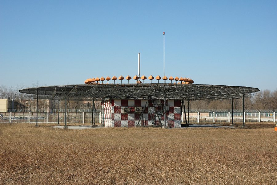
In a conventional VOR (CVOR) the variable signal comes from a directional pattern, a heart-shaped limaçon polar diagram, rotated 30 times a second (1,800 rpm). As the lobe sweeps past, a distant receiver sees the signal strength rise and fall once per revolution, so the variable signal is 30 Hz amplitude modulation (AM) whose phase depends on direction. The reference is frequency-modulated (FM) onto a subcarrier so that the receiver can separate the two.
A Doppler VOR (DVOR) swaps the roles. A central antenna radiates the reference as 30 Hz AM, while a ring of several dozen aerials around it is switched in sequence to simulate one aerial circling 30 times a second. Its movement towards and away from each receiver adds a Doppler shift, producing a 30 Hz frequency modulation whose phase depends on bearing. The phase relationship on every radial is the same as for a CVOR, so the airborne receiver cannot tell them apart.
| CVOR | DVOR | |
|---|---|---|
| Reference signal | 30 Hz FM on a subcarrier | 30 Hz AM |
| Variable signal | 30 Hz AM from the rotating limaçon | 30 Hz FM from the Doppler effect |
| Antenna aperture | Small | Wide ring of aerials |
| Site error | Larger | Much smaller |
The VOR receiver and TO/FROM indication
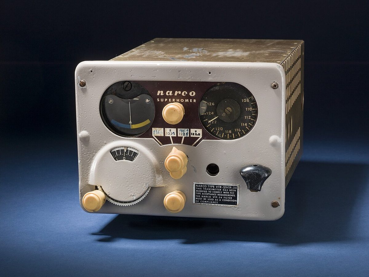
The same VHF navigation receiver serves VOR and ILS localiser, depending on the frequency tuned. On a basic indicator the pilot turns the omni-bearing selector (OBS) to choose a course, and the instrument shows:
- the course deviation indicator (CDI), a needle showing angular displacement from the selected course;
- the TO/FROM indicator, showing whether the selected course, flown from the present position, would lead towards or away from the station;
- a warning flag when the signal is unusable.
On a five-dot CDI each dot is 2° and full-scale deflection is 10°; on an HSI with two dots each side, each dot is typically 5°. A localiser needle is about four times as sensitive (see ILS). Because the needle shows an angle, the distance it represents grows with range: by the 1-in-60 rule, 2° at 45 NM is 1.5 NM off the radial.
The TO/FROM flag depends only on position. Picture a line through the station at right angles to the selected course: on one side the flag reads TO, on the other FROM, and on the line itself it shows OFF or flickers. With the needle centred, OBS 040 and FROM put the aircraft on the 040 radial; OBS 040 and TO put it on the 220 radial, south-west of the station. Turning the aircraft changes neither the needle nor the flag.
The CDI acts as a command instrument only when the OBS roughly matches the direction of flight: the needle then lies towards the course and the pilot steers towards it. Leave the OBS on the reciprocal, for instance tracking inbound on the 090 radial (heading 270) with 090 still selected, and the needle shows reverse sensing: corrections must be made away from it. The rule is to set the inbound course and check TO when inbound, and the radial and FROM when outbound. An HSI cannot reverse sense: its deviation bar rotates with the course pointer, showing the course in plan view. An RMI or bearing pointer needs no selection at all: the head of the needle gives the QDM, the tail the radial.
Exam tip: read the flag first. OBS 090, FROM, needle two dots right: the aircraft is east of the station, the 090 radial lies to its right (south), so it is about 4° north of it, on R-086.
Exam tip: for time to station, put the station on the wingtip and time a bearing change: minutes to the station = seconds flown ÷ degrees of change. A 10° change in 120 seconds means 12 minutes.
Cone of confusion and station passage
Directly above the antenna the bearing signals cannot be resolved. In this conical volume, the cone of confusion, the needle swings, the TO/FROM indication flickers and the warning flag may appear, and the cone widens with height. Some texts call it the cone of silence, a term that fits the NDB better. The FAA simply notes that a conical area above a navaid is generally unusable.
Station passage is the reversal of the TO/FROM indication, not the first movement of the needle. At some stations, usually in mountains, brief needle swings resembling station approach occur well away from the beacon, so the FAA treats the flag change as the positive sign. The same reversal marks the start of the turn outbound when holding at a VOR (see holding patterns) and, on a VOR approach with the station on the airport and no final approach fix, marks the missed approach point.
Site error, scalloping and course bends
The AIM puts the course alignment of a VOR generally within ±1°. Most of the larger errors come from reflections or interference:
- Site error comes from obstacles close to the station, such as buildings, fences, trees or sloping ground, whose reflections distort the radials in certain directions. It belongs to the installation and is much smaller at a DVOR.
- Scalloping is a rapid, regular wander of the needle either side of centre, caused by reflections from terrain or large buildings combining with the direct wave. The pilot flies the average and does not chase the needle.
- A course bend is the slow version of the same thing: a radial that curves gently enough for the aircraft to follow it away from the intended track.
- Certain propeller or rotor speeds modulate the signal and can make the CDI fluctuate by up to ±6°; a small change of rpm normally cures it.
- FM broadcast interference comes from stations in the 88 to 108 MHz band, just below the VOR band. Since the late 1990s, the VHF navigation receivers that serve VOR and ILS have had to include FM suppression circuits.
ATPL textbooks combine about ±3° of airborne error with the ground error into a total of about ±5°. By the 1-in-60 rule that is 2.5 NM either side at 30 NM and 5 NM at 60 NM: the error of a VOR position line grows with distance, whereas the slant-range error of a DME shrinks.

Service volumes and the VOR MON
The FAA publishes a standard service volume (SSV) for each VOR, the airspace in which it assures adequate signal strength and course quality, free of interference. Heights are above the transmitter (ATH), and terrain masking is not included.
| SSV class | Coverage (heights above the transmitter) |
|---|---|
| T (Terminal) | 1,000 to 12,000 ft, to 25 NM |
| L (Low) | 1,000 to 18,000 ft, to 40 NM |
| H (High) | 1,000 to 14,500 ft to 40 NM; 14,500 to 60,000 ft to 100 NM; 18,000 to 45,000 ft to 130 NM |
| VL (VOR Low) | 1,000 to 5,000 ft to 40 NM; 5,000 to 18,000 ft to 70 NM |
| VH (VOR High) | 1,000 to 5,000 ft to 40 NM; 5,000 to 14,500 ft to 70 NM; above that as H |
The SSV governs off-route navigation; published airways and procedures may use a VOR beyond it where the FAA has verified the signal. On FAA en route charts, a minimum obstruction clearance altitude (MOCA) assures VOR reception only within 22 NM of the station. ICAO and EASA use the designated operational coverage (DOC) instead: the range and height within which the frequency is protected from interference. Because VHF has no sky wave, a VOR's DOC is valid by day and by night, unlike an NDB's.
The FAA is withdrawing VORs as performance-based navigation replaces them, but keeps the VOR Minimum Operational Network (VOR MON) as a back-up for GPS outages. It gives almost continuous reception at 5,000 ft above ground across the contiguous United States outside the Western U.S. Mountainous Area, where nearly all VORs remain, and keeps every aircraft within 100 NM of a MON airport with an ILS or VOR approach; the VL and VH volumes were created for it. In Europe, the PBN implementing rule, Regulation (EU) 2018/1048, similarly allows conventional procedures to be kept after 6 June 2030 only for contingencies.
Receiver checks and the VOT
Under 14 CFR 91.171, a VOR receiver may be used under IFR only if it is maintained under an approved procedure or has been operationally checked within the preceding 30 days. The person making the check records the date, place, bearing error and their signature. No correction other than the manufacturer's correction card may be applied.
| Check | Maximum bearing error |
|---|---|
| VOT, or a repair station's radiated test signal | ±4° |
| Designated ground checkpoint on the airport | ±4° |
| Designated airborne checkpoint, or a prominent landmark on an airway, preferably more than 20 NM from the VOR | ±6° |
| Two receivers tuned to the same station | 4° between them |
A VOR test facility (VOT) radiates a test signal that places every receiver on the 360 radial. With the CDI centred, the OBS should read 360 with FROM or 180 with TO, and an RMI points to 180 whatever the OBS setting. A VOT is identified by a series of dots or a continuous tone. It is meant for use on the ground; airborne use is allowed only in the areas and at the altitudes published in the Chart Supplement. A radio repair station may radiate a test signal, normally on 108.0 MHz, by arrangement only. The FAA also recommends yearly recalibration: a deteriorating receiver can pass a check close to a VOT yet be out of tolerance where signals are weaker.
Exam tip: the 30-day check is an FAA rule, but both FAA and EASA questions test the VOT: "360 FROM, 180 TO". Every aircraft appears due north of the station, so an RMI needle points 180.
Frequently asked questions
What is a VOR radial?
A radial is a magnetic bearing measured outwards from a VOR station. An aircraft due east of the station is on the 090 radial whatever its heading. Radials are magnetic because each VOR is aligned with magnetic north at its site. In Q-code terms the radial is the QDR, and its reciprocal, the magnetic bearing to the station, is the QDM.
How does a VOR work?
The station radiates two 30 Hz signals. The reference signal has the same phase in every direction; the variable signal's phase changes with bearing, lagging the reference by an angle equal to the magnetic bearing from the station. The airborne receiver measures that phase difference and displays it as the radial. In a conventional VOR the variable signal comes from a rotating antenna pattern; in a Doppler VOR it comes from the Doppler effect of a simulated rotating aerial.
What is reverse sensing on a VOR?
Reverse sensing occurs when the course set on the omni-bearing selector is roughly opposite to the direction of flight, for example tracking inbound on the 090 radial with 090 still selected. The needle then deflects away from the course and the pilot must correct away from it. Setting the inbound course and checking TO, or the radial and checking FROM when outbound, avoids it; an HSI never reverse senses.
What are the VOR check tolerances?
Under FAA rule 14 CFR 91.171, a VOR used under IFR must have been checked within the preceding 30 days. The maximum error is plus or minus 4 degrees with a VOT or at a designated ground checkpoint, plus or minus 6 degrees at an airborne checkpoint, and 4 degrees between two receivers checked against each other. The date, place, bearing error and signature must be recorded.
How far can you receive a VOR?
VOR is VHF and limited to line of sight, so range grows with altitude and terrain can mask the signal. The FAA protects Terminal VORs to 25 NM up to 12,000 ft above the transmitter, Low VORs to 40 NM up to 18,000 ft and High VORs to 130 NM between 18,000 and 45,000 ft. ICAO and EASA publish a designated operational coverage instead, valid by day and night.
Test yourself on VHF Omnidirectional Range (VOR)
The v1prep banks cover this topic in General and Radio Navigation (061/062), with a worked explanation for every answer. EASA ATPL, PPL, IR and CPL, the FAA written tests and A320/B737 type ratings.
Start practising →Sources and further reading
- FAA Aeronautical Information Manual, Chapter 1 Section 1 (1-1-3 VOR, 1-1-4 VOR Receiver Check, 1-1-8 NAVAID Service Volumes)
- 14 CFR 91.171, VOR equipment check for IFR operations
- ICAO Annex 10, Aeronautical Telecommunications, Volume I, Radio Navigation Aids (copy published by IACM Mozambique)
- FAA Instrument Flying Handbook (FAA-H-8083-15B), Chapter 9, Navigation Systems
- FAA Pilot's Handbook of Aeronautical Knowledge (FAA-H-8083-25), Chapter 16, Navigation
- FAA Aeronautical Chart Users' Guide
Library articles are written for study and exam preparation. They do not replace your aircraft's approved documentation, your operator's procedures or the regulations themselves.