Takeoff Flight Path and Obstacle Clearance
The take-off flight path is the one-engine-inoperative climb from the screen height at the end of the take-off distance to at least 1,500 ft. Obstacle clearance is shown on the net flight path, the gross path reduced by a fixed gradient margin, which must clear every obstacle in a defined area by at least 35 ft.
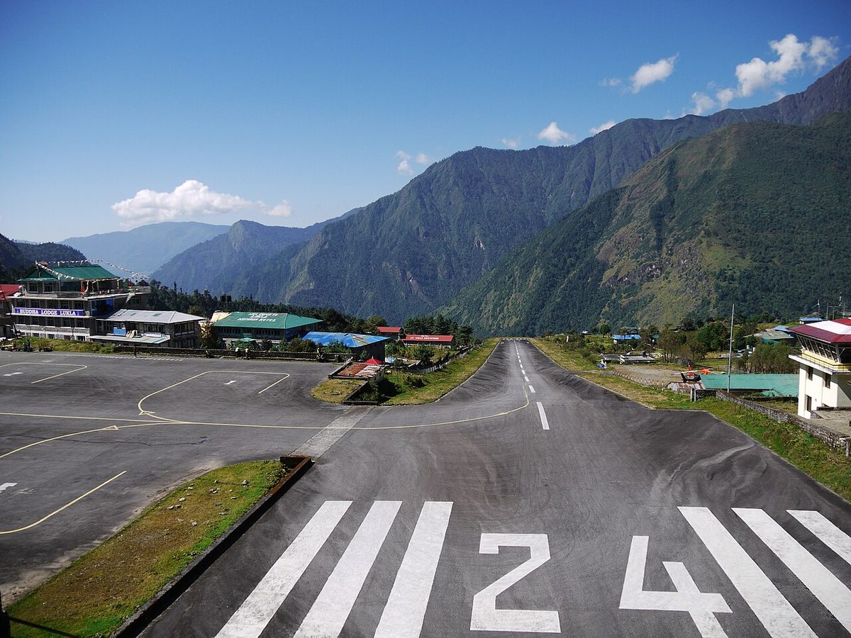
A take-off is not complete when the aeroplane leaves the runway. If an engine fails, the aeroplane must still clear the buildings, masts, trees and terrain beyond the runway end while it climbs on the remaining engines. For Performance Class A aeroplanes the rules do not leave this to chance or to the published departure. Every departure is planned so that a deliberately pessimistic version of the one-engine-inoperative climb, the net take-off flight path, clears every relevant obstacle with a margin.
The requirement sits in CAT.POL.A.210 of EASA's Part-CAT and in 14 CFR 121.189 in the United States, built on the flight path data certified under CS 25.115 and 14 CFR 25.115. Where the obstacles cannot be cleared at the planned mass, the mass must come down, or the operator must design a different path around them. The obstacle limit is one of the take-off mass limits (see take-off mass limitations).
Gross and net take-off flight path
The take-off flight path begins at the screen height at the end of the take-off distance, normally 35 ft, and ends at 1,500 ft above the take-off surface or at the point where the transition to the en-route configuration is complete, whichever is higher. It follows the take-off climb segments: gear retraction, the second segment at V2, level acceleration with flap retraction, and the final climb at maximum continuous thrust. The critical engine is assumed to have failed at VEF throughout.
The gross flight path is the path the aeroplane is expected to fly, based on its certified performance data. The net flight path is the gross path reduced at every point by a fixed gradient:
| Number of engines | Gradient reduction | Second segment, gross to net | Final segment, gross to net |
|---|---|---|---|
| Two | 0.8 % | 2.4 % to 1.6 % | 1.2 % to 0.4 % |
| Three | 0.9 % | 2.7 % to 1.8 % | 1.5 % to 0.6 % |
| Four | 1.0 % | 3.0 % to 2.0 % | 1.7 % to 0.7 % |
The reduction covers what the gross data cannot: variations between individual aeroplanes, in piloting technique and in the atmosphere. The margin is built into the calculation by rule, not left to the crew. Obstacle clearance is always demonstrated on the net path, never on the gross path.
A simplified example shows the scale. If a twin's net path climbed at a constant 1.6 per cent from 35 ft, it would be about 297 ft above the take-off surface 5,000 m further on. An obstacle 250 ft high at that point is cleared by about 47 ft and is acceptable; one 280 ft high is cleared by only 17 ft, so the mass must come down or the departure must change.
Gradients are measured through the air. A headwind steepens the path over the ground and a tailwind flattens it. At a hot or high aerodrome the engines deliver less thrust, so the gradient itself is smaller.
Reference zero
Reference zero is the point on the ground directly below the point where the aeroplane reaches the screen height at the end of the take-off distance. The take-off flight path is drawn from it, and the horizontal distance of each obstacle is expressed as a distance from reference zero.
Reference zero moves with the take-off distance required. If the take-off distance on the day is 2,500 m on a 3,000 m runway, reference zero lies 500 m before the runway end, and an obstacle 2,000 m beyond the runway end is 2,500 m from reference zero. A heavier aeroplane or a hotter day moves reference zero further along the runway, which is why obstacle limits are computed for each set of conditions rather than read once from a chart.
Take-off flight path area
To assess the path, the operator needs to know what stands under it. ICAO Annex 4 provides for an Aerodrome Obstacle Chart, ICAO Type A (Operating Limitations), which shows the significant obstacles in the take-off flight path area of each runway; AIP aerodrome entries refer to these obstacle charts. Operators and specialist providers combine these surveys with other obstacle data to build the runway analyses used by crews.
These charts and surveys serve performance planning. They are not the same as the take-off climb surface of ICAO Annex 14, which protects the airspace around the aerodrome (see obstacles and obstacle limitation surfaces), or the obstacle identification surface used to design a SID.
Obstacle accountability area
Not every obstacle within sight of the runway counts. EASA's CAT.POL.A.210 defines an obstacle accountability area that starts narrow and widens with distance, reflecting growing uncertainty in the aeroplane's position.
The net flight path must clear each obstacle by the vertical margin, or pass it at a horizontal distance of at least 90 m plus 0.125 D, where D is the distance travelled from the end of the take-off distance available. If a turn is scheduled before the end of the take-off distance available, D is measured from the end of the take-off distance instead. For an aeroplane with a wingspan of less than 60 m, the 90 m may be replaced by half the wingspan plus 60 m. For an A320 without sharklets, with a span of 34.1 m, the half-width is then about 77 m plus 0.125 D: about 202 m at 1,000 m from the start of the area.
The widening stops at a maximum lateral distance, beyond which obstacles need not be considered:
| Intended track changes | Required navigational accuracy maintained | All other conditions |
|---|---|---|
| Not more than 15° | 300 m | 600 m |
| More than 15° | 600 m | 900 m |
For the A320 on a straight departure with the required navigational accuracy, the half-width reaches its 300 m limit about 1,800 m from the start of the area.
The FAA's 121.189 takes a different form: the net take-off flight path must clear each obstacle by 35 ft vertically, or by 200 ft horizontally within the airport boundaries and 300 ft after passing them. FAA AC 120-91 gives the accepted methods for defining the obstacle accountability area, including for turning departures.
Required obstacle clearance
The vertical margins are small because the net path is already pessimistic:
- the net flight path must clear every obstacle in the accountability area by at least 35 ft;
- in any part of the net flight path where the aeroplane is banked by more than 15°, the margin is 50 ft.
The planned path is also constrained in bank. No turn is assumed until the net flight path has reached a height of half the wingspan, and at least 50 ft, above the end of the take-off run available. Up to 400 ft the aeroplane is assumed to bank no more than 15°; above 400 ft, bank angles of more than 15°, up to 25°, may be scheduled. The effect of the bank on speeds and on the flight path must be allowed for.
The operator must also establish contingency procedures that meet these requirements and give a safe route, avoiding obstacles, to a point from which the aeroplane can either meet the en-route requirements or land back at the departure aerodrome or at a take-off alternate (see one-engine-inoperative en-route performance).
Exam tip: 35 ft is the obstacle clearance of the net take-off flight path, and 35 ft is also the Class A screen height, but they are different requirements. The first is a margin over obstacles, the second the height at which the take-off distance ends.
Turning departures
A turn can take the aeroplane away from high ground straight ahead, but it has a price. In a level turn the load factor is 1 ÷ cos(bank): about 1.04 at 15° and 1.15 at 30°. The extra lift raises induced drag, so the climb gradient falls. A track change of more than 15° widens the accountability area from 300 m to 600 m, or from 600 m to 900 m, and a bank above 15° raises the vertical margin to 50 ft. The turn radius also grows with true airspeed, which matters at hot and high aerodromes.
The certified speeds allow for turning. V2 must be high enough for a coordinated turn at 30° of bank with the critical engine inoperative without stall warning (see take-off speeds V1, VR and V2), and on the 737 the bank is limited to 15° until V2 + 15 kt.
Engine-out SID
A published standard instrument departure protects only an aeroplane that follows its track and achieves its climb gradient with all engines operating. ICAO PANS-OPS designs departures for a gradient of 3.3 per cent unless a higher one is published; the FAA's equivalent is 200 ft per NM (see instrument departures). A twin's net second-segment gradient is 1.6 per cent. Flying the SID after an engine failure therefore gives no assurance of obstacle clearance.
Operators close that gap with an engine-out standard instrument departure (EOSID), also called an engine failure procedure or engine-out procedure, designed by the operator or a specialist provider for each runway. It gives the track to fly, any turn and where it begins, the engine-out acceleration altitude and the end point: typically a hold, a return to the aerodrome, or a route to a height from which the en-route requirements can be met. Early turns in such procedures, towards lower terrain, rely on the analysis of the accountability area described above.
The engine-out procedure is part of every take-off briefing. After an engine failure the crew flies it rather than the SID, tells ATC, and flies it accurately. It clears the obstacles only with the speeds, bank angles and acceleration height it was designed for.
Frequently asked questions
What is the net take-off flight path?
The net take-off flight path is the one-engine-inoperative flight path reduced at every point by a fixed climb gradient, 0.8 per cent for a twin, 0.9 per cent for a three-engined and 1.0 per cent for a four-engined aeroplane. The reduction covers variations in aircraft performance, piloting and atmosphere. Obstacle clearance is always shown on the net path, never on the gross path the aeroplane is expected to fly.
How much obstacle clearance is required after take-off?
Under EASA's CAT.POL.A.210 and the FAA's 14 CFR 121.189, the net take-off flight path must clear every obstacle in the area to be considered by at least 35 ft vertically. EASA raises the margin to 50 ft wherever the aeroplane is banked by more than 15°. Obstacles far enough to the side of the track, beyond the lateral limits of the area, need not be considered.
What is reference zero?
Reference zero is the point on the ground directly below the point where the aeroplane reaches the screen height, normally 35 ft, at the end of the take-off distance. The take-off flight path is drawn from it, so the horizontal distance of every obstacle is converted into a distance from reference zero before the clearance is checked. Its position moves with the take-off distance required on the day.
What is an engine-out SID?
An engine-out SID, or engine failure procedure, is a departure route designed by the operator for use when an engine fails during take-off. The published SID gradient assumes all engines operating, so it does not protect an engine-out climb. The engine-out procedure gives the track, any turns and the acceleration altitude that keep the net flight path clear of obstacles, and where to go afterwards.
Why does a turn after take-off reduce obstacle clearance margins?
In a banked turn the wing must produce more lift than the weight, which raises induced drag and reduces the climb gradient. A turning departure also needs a wider area to be surveyed for obstacles, and where the bank exceeds 15° EASA requires 50 ft of clearance instead of 35 ft. Turns are therefore planned only where they avoid higher obstacles straight ahead.
Test yourself on Takeoff Flight Path and Obstacle Clearance
The v1prep banks cover this topic in Performance (032), with a worked explanation for every answer. EASA ATPL, PPL, IR and CPL, the FAA written tests and A320/B737 type ratings.
Start practising →Sources and further reading
- EASA, Easy Access Rules for Air Operations (CAT.POL.A.210, Take-off obstacle clearance)
- 14 CFR 25.115, Takeoff flight path
- 14 CFR 121.189, Airplanes, turbine engine powered, takeoff limitations
- FAA AC 120-91, Airport Obstacle Analysis
- ICAO Annex 4, Aeronautical Charts
- EASA, Easy Access Rules for Large Aeroplanes (CS-25)
Library articles are written for study and exam preparation. They do not replace your aircraft's approved documentation, your operator's procedures or the regulations themselves.