Head-Up Display and Vision Systems
A head-up display (HUD) projects flight symbology onto a transparent combiner in the pilot's forward view, focused at infinity so that it overlies the outside scene. Vision systems add an image to it or to other displays: a live sensor view (enhanced vision) or a view generated from a database (synthetic vision).
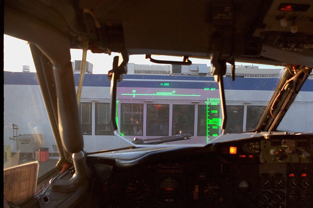
A head-up display (HUD) puts the most important flight information in front of the pilot's eyes instead of on the instrument panel below them. Symbols for flight path, speed, altitude and guidance are projected onto a transparent glass, the combiner, through which the pilot keeps looking at the runway. On approach, in low visibility and in the flare, the pilot no longer has to shift gaze and focus between instruments and the outside world.
Two families of vision systems build on the same idea. An enhanced vision system (EVS) shows a live image from a sensor, typically an infrared camera that can show approach lights through haze and darkness. A synthetic vision system (SVS) draws a picture of terrain, obstacles and the runway from a database. The rules treat them very differently: under FAA rules a certified enhanced image on a HUD can, under conditions, stand in for the pilot's own eyes below the decision height, while a synthetic image never can.
Head-up display principle
HUDs were first developed for military aircraft and later adapted for transport aircraft, where they allow precise, manually flown approaches and landings. A transport HUD has three main parts:
- a projector, which generates the image of the symbology;
- a combiner, a transparent, partly reflecting glass between the pilot and the windscreen, which reflects the symbology towards the pilot while letting the outside view through;
- a computer that draws the symbols from the aircraft's inertial, air data, navigation and guidance data.
The symbology is visible only with the pilot's eyes close to the design eye position, so seat adjustment matters, as it does for the view over the nose in low visibility (see low visibility operations). HUDs are often fitted on the left seat only; the 737's Rockwell Collins head-up guidance systems (HGS-4000 and HGS-6000) are optional equipment, and the FAA's Flight Standardization Board found a right-seat HUD and dual HUD operations operationally suitable in 2018. On the A320, where a HUD is an option, a pilot with the combiner deployed must turn the head towards the other pilot to don the oxygen mask quickly.
HUD symbology and collimation
The HUD image is collimated: the optics place it at infinity, the same focus as the distant scene. The pilot can read the symbols and see the runway at the same time without refocusing, which saves precious seconds in the critical phases of take-off, low visibility approach and autoland monitoring. Because the image is at infinity, it does not slide across distant objects when the pilot's head moves slightly, so symbols can be conformal, drawn exactly over the real features they represent.
The most important conformal symbol is the flight path symbol, or flight path vector, which shows where the aircraft is actually going rather than where the nose points. Placed on the touchdown zone, it shows that the aircraft will reach it; drift appears as the symbol's sideways offset. The FAA's 737 training requirements list the symbology that is unique to the HUD:
- the flight path symbol;
- flight path acceleration, showing whether the aircraft is accelerating or decelerating along its flight path;
- an airspeed error tape, showing the deviation from the selected speed;
- an angle of attack limit bracket, showing the margin to the angle of attack limit;
- excessive pitch chevrons, pointing back towards the horizon in extreme attitudes.
A conformal horizon line, a synthetic runway outline and a guidance cue complete the picture. In the guidance modes the pilot steers the flight path symbol onto a guidance cue, much as a flight director is followed. The FSB also requires training in how the symbology behaves in windshear, with erratic flight path, flight path acceleration and speed error indications.
HUD landing systems
A head-up display landing system (HUDLS) is the complete airborne system that gives head-up guidance for the approach, landing and go-around, allowing a manually flown landing in conditions that would otherwise require an autoland. It earns operational credits in both regulatory systems.
In the FAA system, AIM 1-1-9 lists the lowest ILS minimums:
| Operation | Minimums | HUD role |
|---|---|---|
| CAT I | DH 200 ft, RVR 2,400 ft | RVR 1,800 ft with autopilot, flight director or HUD |
| SA CAT I | DH 150 ft, RVR 1,400 ft | HUD to DH required |
| CAT II | DH 100 ft, RVR 1,200 ft | RVR 1,000 ft with autoland or HUD to touchdown, when authorised |
| SA CAT II | DH 100 ft, RVR 1,200 ft | Autoland or HUD to touchdown, with reduced lighting |
For take-off, an FAA Part 121 operator's specifications can authorise RVR 300 ft with an approved take-off guidance system such as a HUD. Under EASA's all-weather rules in force since 30 October 2022, a take-off below 400 m RVR needs an approval under Part-SPA, Subpart LVO. Below 125 m the flight manual minimum applies, never less than 75 m, and the runway must have protection and facilities equivalent to CAT III landing operations and the aircraft an approved lateral guidance system, of which a head-up guidance system is one example. Under the EU-OPS rules replaced in October 2022, a fail-passive CAT IIIA or IIIB approach, or one flown with a HUDLS, needed a segment of at least three consecutive lights at the decision height.
Type limitations show the trade. On the A320, the crew flying an other-than-standard (now special authorisation) CAT II approach with a HUD must use it to monitor the approach and may finish with an automatic or a manual landing; if the autopilot flies the approach without autoland, it must be disengaged by 80 ft. Without the HUD, an automatic landing is required. Embraer's E190 E1 is listed with a head-up guidance system for low visibility take-off, CAT IIIa and roll-out, a capability the E190-E2 does not have.
The credit is earned by training. For the 737 the FSB requires, before a captain uses the HUD in instrument conditions below RVR 1,800 ft, at least 25 manually flown HUD approaches to CAT II/IIIa minima in visual conditions, each ending in a HUD-assisted landing or go-around, and 25 HUD-assisted take-offs. Periodic checks should still demonstrate non-HUD skills. A draft revision of the same report extends HUD training to head-worn displays with a virtual HUD.
Enhanced vision systems
An enhanced vision system displays a real-time image of the outside scene from forward-looking sensors. An enhanced flight vision system (EFVS) is an EVS presented on a HUD, or an equivalent head-up display, together with flight information and guidance, and certified for use instead of natural vision. The AIM describes the benefit: the pilot can see approach lights, runway features and other objects that natural vision would not yet show, while looking forward along the flight path through approach, landing and roll-out.
The FAA's 14 CFR 91.176 recognises two EFVS operations:
- EFVS to touchdown and roll-out, under 91.176(a), only on approaches with a DA or DH, and only with a specific authorisation (operations specification, management specification or letter of authorisation);
- EFVS to 100 ft above the touchdown zone elevation, under 91.176(b), on approaches with a DA/DH or an MDA; below 100 ft the pilot must see the required references with natural vision. Part 91 operators other than 91K need no letter of authorisation for this in the United States.
Neither is permitted on an approach with circling minima. To descend below minima the pilot must judge that the enhanced flight visibility is at least that required by the procedure and must see the required visual references distinctly on the EFVS. The AIM is explicit that an EFVS does not lower the DA/DH, MDA or visibility of the approach; it is another means of flying the visual segment. If a required component fails, a missed approach is required, although the pilot may still continue if that is judged safer. Pilots need specific ground and flight training and recent experience.
Warning: infrared-based EFVS cannot sense LED lights. As airports replace incandescent lamps with LEDs, the approach lights may be invisible on the sensor image; US airports with LED approach lighting carry the Chart Supplement remark "Pilots conducting EFVS ops; be aware LED ALS in use".
EASA's all-weather rules take a more cautious step. Under CAT.OP.MPA.312 an EFVS 200 operation lets an equipped aircraft use reduced RVR minima, but never below 550 m, with the DH not below 200 ft, so it is not a low visibility operation and needs no specific approval (see visibility and RVR).
Synthetic and combined vision systems
A synthetic vision system presents a computer-generated, three-dimensional view of terrain, obstacles and runways, built from a database and the aircraft's position and attitude, on a head-down or head-up display. It gives excellent awareness of terrain, but it is not a view of the real world: it shows no real-time image, does not reveal an aircraft or vehicle on the runway, and is only as good as its database and position source.
The rules follow. The AIM states that a synthetic vision image, head-up or head-down, may not be used instead of natural vision to descend below DA/DH or MDA. Operators add their own limits: on the E190-E2, SVS must not be used as a primary navigation source, the operator requires it on below the minimum sector altitude, and it shows the extended runway centreline rather than the approach course, with the bottom of the runway box abeam the touchdown zone.
A combined vision system (CVS) merges enhanced and synthetic images. The AIM allows a CVS to be used for EFVS operations if all EFVS requirements are met and the synthetic part does not interfere with the pilot's view of the outside scene, the required visual references or the sensor image.
Para-visual displays
A para-visual display (PVD) takes the head-up idea in a different direction: instead of symbols to be read, it gives a cue to be sensed in peripheral vision while the eyes stay on the outside world. The classic example is roll-out guidance after an automatic landing in very low visibility. A striped cylinder, like a barber's pole, rotates to show which way to steer to regain the centreline, its command proportional to the localiser deviation. The alternative is automatic steering through the rudder and nosewheel.
Roll-out guidance mattered for the lowest minima. Under EU-OPS, the controlling minimum for the midpoint RVR fell from 125 m to 75 m where roll-out guidance or control was fitted, and roll-out guidance remains part of the capability statements in flight manuals and type certificate data sheets.
Limitations and human factors
A HUD adds information in the one place the pilot is already looking, which is both its strength and its risk. The FSB emphasises clear pilot flying and pilot monitoring duties, because HUD failure modes can reduce precision and increase workload unless each pilot knows the role. With a single HUD only one pilot can be head-up, so the pilot monitoring watches the head-down instruments and the automation, and the procedural callouts bridge the two.
Vision systems carry a subtler trap. A bright sensor or synthetic image can suggest more visual reference than natural vision would give. The rules therefore separate the approach minima, which the systems do not change in the FAA framework, from the means of meeting the visual reference requirement, and they require a go-around when the picture, the equipment or the pilot's own view is not good enough.
Frequently asked questions
Why is a head-up display collimated?
Collimation puts the image of the symbology at optical infinity, the same focus as distant objects outside. The pilot can therefore read speed, flight path and guidance while looking at the runway, with no need to refocus from near instruments to the outside scene and back. It also keeps conformal symbols, such as the horizon line and the flight path symbol, aligned with the real world they represent.
What is the difference between EVS, EFVS and SVS?
An enhanced vision system shows a real-time image of the outside scene from a sensor, typically infrared. An enhanced flight vision system is an EVS shown on a HUD or equivalent head-up display and certified so that its image may be used instead of natural vision in the visual segment of an approach. A synthetic vision system draws the scene from a terrain and obstacle database; it shows no real-time image and cannot replace natural vision below minima.
Does an EFVS allow lower minima?
Not in the FAA system. The AIM states that using an EFVS does not lower the DA, DH, MDA or visibility of the approach; it provides another means of operating in the visual segment. Under 14 CFR 91.176 the pilot may descend below DA/DH or MDA on EFVS imagery, to 100 ft above touchdown zone elevation or, on approaches with a DA or DH and with the required equipment and authorisation, to touchdown. EASA's EFVS 200 gives an RVR credit, but not below 550 m.
What is a HUDLS?
A head-up display landing system is the complete airborne system that gives the pilot head-up guidance for the approach, landing and go-around, allowing a manually flown landing in conditions that would otherwise need an autoland. HUDLS earns operational credits: FAA CAT II minima of RVR 1,000 ft with a HUD to touchdown, SA CAT I and SA CAT II, and low visibility take-offs in very low RVR with approval.
What is a para-visual display in aviation?
A para-visual display is a steering indicator designed to be sensed in peripheral vision while the pilot looks outside. The classic type used for roll-out guidance after an automatic landing is a striped cylinder, like a barber's pole, that rotates to show which way to steer to regain the runway centreline, proportional to the localiser deviation. Roll-out guidance of this kind was one of the aids behind the lowest runway visual ranges.
Test yourself on Head-Up Display and Vision Systems
The v1prep banks cover this topic in Instrumentation (022), with a worked explanation for every answer. EASA ATPL, PPL, IR and CPL, the FAA written tests and A320/B737 type ratings.
Start practising →Sources and further reading
- FAA Aeronautical Information Manual, Chapter 5 Section 4 (5-4-22, Use of Enhanced Flight Vision Systems on Instrument Approaches)
- 14 CFR 91.176, Straight-in landing operations below DA/DH or MDA using an enhanced flight vision system (EFVS)
- FAA Aeronautical Information Manual, Chapter 1 Section 1 (1-1-9, Instrument Landing System, ILS minimums)
- FAA AC 120-118, Criteria for Approval/Authorization of All Weather Operations for Takeoff, Landing, and Rollout
- FAA Flight Standardization Board Report, Boeing 737, Revision 17 (Appendix 5, Head-Up Guidance Training)
- EASA, Explanatory Note to ED Decision 2022/012/R, All-weather operations
- EASA Easy Access Rules for Air Operations (Regulation (EU) No 965/2012), CAT.OP.MPA.312 and Part-SPA Subpart LVO
- EASA, Easy Access Rules for All Weather Operations (CS-AWO)
Library articles are written for study and exam preparation. They do not replace your aircraft's approved documentation, your operator's procedures or the regulations themselves.