Instrument Layout and Scan Technique
Instrument layout is the standard arrangement and colour coding of flight deck instruments, built around the basic T. Scan technique is the disciplined pattern in which a pilot flying by instruments looks at, cross- checks and interprets them to control the aircraft, including after an instrument failure or an unusual attitude.
An instrument panel is designed so that the right information is in the right place, in the same place on every aircraft, and in colours that say at once whether a value is normal. Instrument flying then depends on how the pilot uses that panel: a disciplined instrument scan that looks at each instrument at the right moment, cross-checks one against another and turns what it shows into small, timely control inputs.
Both halves are examined, from the PPL and instrument rating theory to the ATPL instrumentation and human performance papers. The FAA's Instrument Flying Handbook (IFH), FAA-H-8083-15B, is the standard reference for the techniques. The individual instruments are described in articles such as attitude indicator and turn and slip indicators.
Flight deck panels and layout
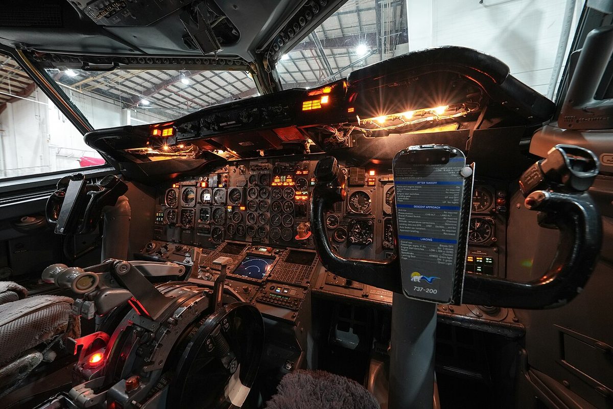
A transport flight deck is divided into areas, each with its own job:
- the main instrument panel, with each pilot's flight instruments directly in front of them and the shared engine, warning and system displays in the centre;
- the glareshield, the shelf above the main panel, carrying the autoflight system's short-term tactical controls, such as the A320's flight control unit or the Boeing 737's mode control panel, so they can be operated head up and within reach of both pilots; the master warning and master caution lights sit on or just below it, in front of each pilot, near the centre of the scan;
- the overhead panel, for the aircraft systems; on the A320 the panels linked to each engine are arranged vertically so that procedures flow logically and errors are reduced;
- the centre pedestal between the seats, carrying the thrust levers, the flight management control display units, the radio management panels, the speedbrake lever and, on the A320, the pitch trim wheels and the ECAM control panel.
Airbus overhead pushbuttons follow the dark cockpit or lights-out philosophy: with every system normal, no pushbutton light is on, so any light draws the eye. Engine instruments are laid out in columns, one per engine, with the same parameter in each row, so that a discrepancy and the engine concerned are seen at a glance. Control shapes help too: CS 25.781 and 14 CFR 25.781 prescribe distinctive knob shapes for controls such as the landing gear and flap levers, so that they are not confused.
The seat must be adjusted to the design eye position before flight. On the A320 the pilot's eyes are in the right place when a red ball and a white light on the centre windscreen post line up. From there every instrument is read without distortion and the view outside is as designed.
The basic T
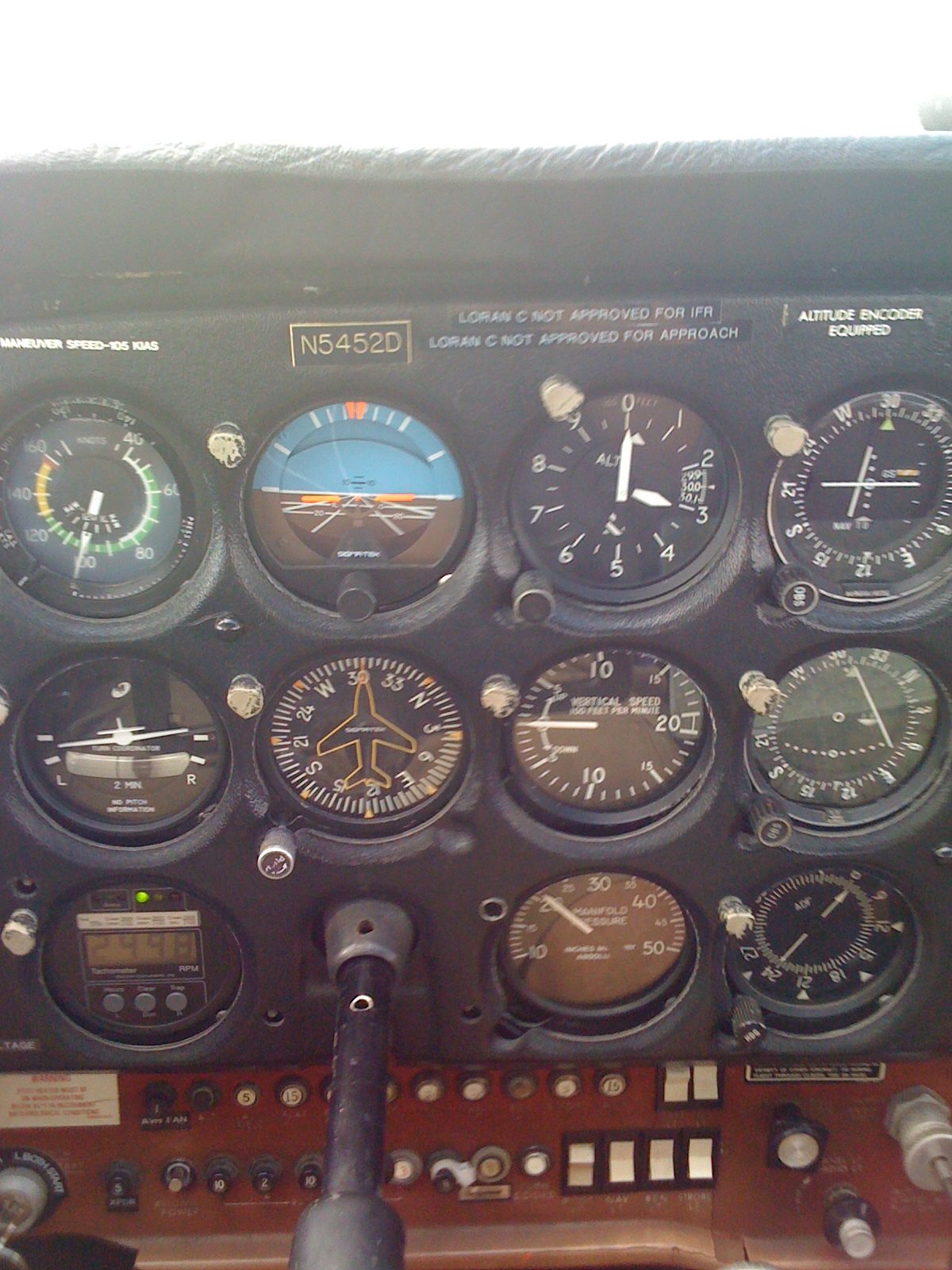
The basic T is the standard arrangement of the four primary flight instruments. The attitude indicator sits at the top centre, directly in front of the pilot, because it is the one instrument that shows pitch and bank directly. The airspeed indicator is on its left, the altimeter on its right and the heading indicator or HSI below it. The vertical speed indicator is normally beside the altimeter and the turn indicator to the left of the heading indicator. The arrangement replaced an older basic six grouping and means a pilot changing type finds the instruments in the same places.
The same logic survives in glass cockpits. A primary flight display puts the attitude in the centre, a speed tape on the left, an altitude tape with the vertical speed on the right and the heading at the bottom, with the flight mode annunciator along the top (see primary flight display). Airliners add a set of standby instruments in the centre panel.
The cockpit clock completes the panel. For IFR flight 14 CFR 91.205(d) requires a clock showing hours, minutes and seconds, and Part-NCO requires a means of displaying time in hours, minutes and seconds even for day VFR. The A320's clock shows UTC in hours, minutes and seconds, the elapsed time from engine start in hours and minutes, and a chronometer in minutes and seconds started with the CHRONO button, and it can show the date. The 737's clocks are GPS-compatible and initialise to UTC when a valid GPS signal is available. The clock times turns, holds and approach segments, and the FMS clock is checked against it before departure because recorded data and ETAs depend on it.
Instrument colour coding
Conventional gauges share one code: green for the normal operating range, yellow or amber for a caution range and red for a limit or warning. The airspeed indicator of a light aeroplane carries the most detailed set of range markings:
| Marking | Meaning |
|---|---|
| White arc | Flap operating range, from VS0 (stall in the landing configuration) to VFE |
| Green arc | Normal operating range, from VS1 to VNO |
| Yellow arc | Caution range, from VNO to VNE: smooth air only |
| Red radial line | VNE, never to be exceeded |
| Blue radial line (light twins) | VYSE, best rate of climb with one engine inoperative |
| Red radial line at the low end (light twins) | VMCA, minimum control speed in the air |
The manoeuvring speed VA is not marked, because it falls as weight decreases; it is found in the flight manual.
Electronic displays extend the code. The display guidance for large aeroplanes (EASA AMC 25-11, FAA AC 25-11) keeps red for warnings and limits and amber for cautions, and uses green for engaged modes, white for scales and current values, cyan for the sky and tan or brown for the earth on the attitude display. Magenta is used for "fly-to" information: flight director commands, deviation pointers, the active route and the active waypoint. ATPL exam material summarises the code with white for the present situation and blue for a temporary one, such as an armed mode waiting to engage; in practice armed modes are white on Boeing displays and blue on Airbus ones. For alerts, CS 25.1322 and 14 CFR 25.1322 require red for warnings, amber or yellow for cautions, and any colour except red or green for advisories. Manufacturers differ in detail, so the flight crew operating manual of the type always rules.

Reading analogue instruments
An analogue instrument display shows a value as the position of a pointer against a scale. Its strength is trend and check reading: the pilot sees at a glance whether a needle is moving, how fast and in which sector, and a row of engine needles all pointing the same way shows at once that the engines agree.
Parallax error is the misreading that occurs when the eye is not on the instrument's design axis, so that the pointer appears against the wrong graduation. Designers reduce it with knife-edge pointers, mirrored scales and the design eye position; the pilot reduces it by adjusting the seat and reading instruments from the normal position, not from across the flight deck.
Instrument scan and cross-check
The IFH describes three fundamental skills of attitude instrument flying: the instrument cross-check or scan, instrument interpretation and aircraft control. In the selected radial or hub-and-spoke scan, the eyes rest on the attitude indicator, glance out to one performance instrument and return to the attitude indicator before the next. The attitude indicator is the hub because it alone shows pitch and bank directly and without lag. The IFH also describes the inverted-V and rectangular patterns; whatever the pattern, no instrument should go unwatched for long.
Three cross-check errors are classic:
- Fixation: staring at one instrument while the rest drift, such as centring the localiser needle while the aircraft sinks below the glide path;
- Omission: leaving an instrument out of the scan altogether;
- Emphasis: relying on one instrument instead of the combination.
The scan also finds failures. If the altimeter and vertical speed indicator show a descent while the attitude indicator shows level flight, the aircraft is descending. A vacuum-driven attitude indicator that is spinning down tilts slowly into a false but believable picture, often without a flag; only a cross-check against the turn indicator, heading and pressure instruments exposes it. Airline crews add comparisons between the two pilots' displays and the standby instruments.
Warning: in cloud the body's sensations are unreliable whenever the aircraft accelerates or turns. The defence against spatial disorientation is a disciplined scan and the decision to believe the instruments.
Control and performance method
The control and performance method divides the instruments by function. The control instruments are the attitude indicator and the power instruments (rpm, manifold pressure, N1, EPR or torque). The performance instruments, altimeter, airspeed indicator, vertical speed indicator, heading indicator and turn indicator, show the result. The pilot sets a known attitude and power, trims, checks the performance instruments and adjusts. Attitude plus power equals performance: a pilot who knows the aircraft's numbers, for example a given rpm and 3° nose-up for 100 kt in level flight, makes small, predictable corrections.
Primary and supporting method
The primary and supporting method names, for each manoeuvre, the primary instrument that gives the most pertinent information for pitch, bank and power, backed by supporting instruments:
| Manoeuvre | Pitch | Bank | Power |
|---|---|---|---|
| Straight and level | Altimeter | Heading indicator | Airspeed indicator |
| Constant-rate climb or descent | Vertical speed indicator | Heading indicator | Airspeed indicator |
| Constant-airspeed climb | Airspeed indicator | Heading indicator | Power set, rpm or manifold pressure |
| Rate-one level turn | Altimeter | Turn indicator | Airspeed indicator |
The attitude indicator is used to make every change in both methods; the primary instrument shows whether the change achieved what was intended. The FAA teaches the two methods side by side.
Partial panel flying
Partial panel or limited panel flying means controlling the aircraft with one or more gyro instruments failed. In a typical light single the attitude and heading indicators are vacuum-driven and the turn coordinator electric, so that one failure cannot remove every gyro. A suction gauge below its normal range, typically 4.5 to 5.5 inHg, warns of the failure.
The technique is to cover the failed instruments and rebuild the scan around what remains:
- bank from the turn coordinator or turn and slip indicator: a level symbol with the ball centred means wings level;
- heading from the magnetic compass, with changes made as rate-one turns of 3° per second timed on the clock, so 180° takes one minute;
- pitch from the altimeter, vertical speed indicator and airspeed indicator.
A glass cockpit fails differently. If its attitude and heading reference system fails, red crosses replace attitude and heading, but the air data tapes remain valid; the pilot flies the standby attitude indicator and the compass. In either case the workload is high: tell ATC and seek visual conditions or a no-gyro approach.
Unusual attitude recovery
The FAA defines an unusual attitude as any attitude not normally required for instrument flight; ICAO and EASA speak of an upset. It is recognised by the whole panel, not one instrument: in a nose-high attitude the airspeed decreases, the altimeter and vertical speed show a climb and the attitude indicator shows pitch up.
For a light aeroplane the IFH recoveries are:
- Nose low, airspeed increasing: reduce power, level the wings with co-ordinated aileron and rudder, then raise the nose smoothly to the level attitude. Pulling before the wings are level tightens the spiral.
- Nose high, airspeed decreasing: add power, lower the nose to prevent a stall, then level the wings.
Without an attitude indicator, the IFH takes the moment when the airspeed and altimeter stop moving and begin to reverse as the sign that the aircraft is passing through level pitch attitude. Transport aeroplanes use the industry recovery templates described in upset prevention and recovery, always subject to the manufacturer's procedures.
Frequently asked questions
What is the basic T instrument layout?
The basic T is the standard arrangement of the four most important flight instruments. The attitude indicator sits at the top centre, directly in front of the pilot, with the airspeed indicator on its left, the altimeter on its right and the heading indicator or HSI below it. The vertical speed indicator usually sits to the right of the heading indicator and the turn indicator to its left. Primary flight displays keep the same arrangement.
What are the three common instrument scan errors?
They are fixation, omission and emphasis. Fixation is staring at one instrument while the others drift, such as centring the localiser while the aircraft sinks below the glide path. Omission is leaving an instrument out of the scan altogether. Emphasis is relying on one instrument instead of the combination, for example on the attitude indicator alone when the altimeter and vertical speed show a descent.
What is the difference between the control and performance method and the primary and supporting method?
Both come from the FAA Instrument Flying Handbook. The control and performance method sets a known attitude and power on the control instruments, then checks the result on the performance instruments. The primary and supporting method names, for each manoeuvre, the instrument that gives the most pertinent information for pitch, bank and power, such as the altimeter for pitch in level flight. The attitude indicator is the control instrument in both.
How do you fly partial panel after a vacuum failure?
Cover the failed attitude and heading indicators so that they cannot mislead. Control bank with the electric turn coordinator: a level symbol with the ball centred means wings level. Take heading from the magnetic compass and make heading changes with rate-one turns timed on the clock, 3 degrees per second. Control pitch with the altimeter, vertical speed and airspeed indicators, tell ATC and seek visual conditions or a no-gyro approach.
What is the recovery from a nose-low unusual attitude in a light aeroplane?
Airspeed is increasing, so reduce power first to stop the acceleration, then level the wings with co-ordinated aileron and rudder, and only then raise the nose smoothly to the level attitude before resetting power and trim. Pulling while banked would tighten a spiral and raise the load factor. The nose-high recovery is the mirror image: add power, lower the nose and level the wings.
Test yourself on Instrument Layout and Scan Technique
The v1prep banks cover this topic in Instrumentation (022), with a worked explanation for every answer. EASA ATPL, PPL, IR and CPL, the FAA written tests and A320/B737 type ratings.
Start practising →Sources and further reading
- FAA Instrument Flying Handbook (FAA-H-8083-15B), Chapters 5 to 8
- FAA Pilot's Handbook of Aeronautical Knowledge (FAA-H-8083-25), Chapter 8, Flight Instruments
- EASA Easy Access Rules for Large Aeroplanes (CS-25), CS 25.781, CS 25.1322 and AMC 25-11 (control knob shapes, flight crew alerting, electronic display colours)
- EASA Easy Access Rules for Air Operations (Regulation (EU) No 965/2012), NCO.IDE.A.120, flight and navigational instruments
- EASA, Explanatory Note to ED Decision 2018/001/R, Part-FCL theoretical knowledge learning objectives (022 Instrumentation, 040 Human Performance)
Library articles are written for study and exam preparation. They do not replace your aircraft's approved documentation, your operator's procedures or the regulations themselves.