Flap Systems
A flap system is the set of controls, computers, drive units, shafts and actuators that extend and retract an aeroplane's trailing-edge flaps to the selected position, keeps the two wings' flaps in step, and protects them against asymmetry, skew, uncommanded movement and excessive air loads.
A flap system turns a lever movement in the cockpit into a precise, symmetrical change in the shape of both wings. How flaps raise the maximum lift coefficient and lower the stall speed is covered in high-lift devices; this article is about the machinery. On a transport aeroplane a computer reads the flap lever, a central drive unit turns shafts that run along both wings, and actuators at every flap track move the panels together. Monitoring watches the result and stops everything if the two wings disagree.
The protections matter because flaps carry very large air loads and sit far from the aeroplane's centreline. An overspeed can damage their structure, and a flap that extends on one wing but not the other produces a rolling moment, and a yawing one, that may be more than the ailerons can hold. Most flap failures leave a flyable aeroplane, but one that must land faster, with a longer landing distance, and with a crew who must not make things worse by recycling a lever that a protection has deliberately frozen.
Flap lever and control
The flap lever sets the configuration. It moves between detents or gates, so the pilot must deliberately lift or pull it from one position to the next and cannot skip intermediate settings by accident. Each position has its own limit speed, VFE, on the placard.
On the A320 the lever has five positions, 0, 1, 2, 3 and FULL, and each controls slats and flaps together. The lever must be pulled out of its detent before it moves, balks at positions 1 and 3 stop a single movement from calling for too much travel, and no intermediate position can be selected.
| A320 lever | Configuration | Slats / flaps | VFE |
|---|---|---|---|
| 1 | CONF 1 (in flight) | 18° / 0° | 230 kt |
| 1 | CONF 1+F (take-off) | 18° / 10° | 215 kt |
| 2 | CONF 2 | 22° / 15° | 200 kt |
| 3 | CONF 3 | 22° / 20° | 185 kt |
| FULL | CONF FULL | 27° / 35° | 177 kt |
These are A320 figures. On A320s with IAE or CFM LEAP-1A engines FULL is 27°/40°, at the same VFE, and the A321's angles and limits differ.
The Boeing 737 lever has the positions UP, 1, 2, 5, 10, 15, 25, 30 and 40. Flap gates at 1 and 15 stop inadvertent movement beyond them, the positions checked for a one-engine-inoperative and a normal go-around. The leading-edge devices follow the lever: at flaps 1, 2 and 5 the leading-edge flaps are fully extended and the slats move to an intermediate extended position, and beyond 5 the slats extend fully. Both types limit flap extension to 20,000 ft.
Between the lever and the surfaces sits a computer: two slat/flap control computers (SFCCs) on the A320, each with a slat and a flap channel, and the flap slat electronic unit (FSEU) on the 737. They command the drive, monitor the surfaces and run the protections. On the A320 the speed limit shown on the PFD follows the lever, while the overspeed warning follows the actual surface position, so a brief overspeed warning can appear while the flaps are still travelling.
Power drive unit and torque tubes
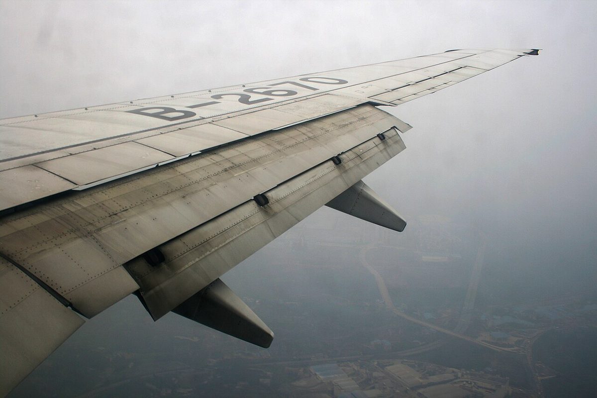
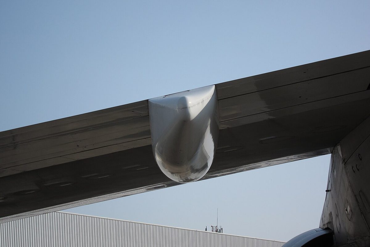
Large aeroplanes drive the trailing-edge flaps from one central power drive unit (PDU), which Airbus calls a power control unit. It turns a transmission of spanwise shafts, the flap torque tubes, that run along each wing to screwjacks or other actuators at every flap station. Because every panel on both wings is driven through the same mechanical chain, left and right flaps move together, and the computers watch that they do.
The drive unit is itself duplicated:
- Airbus A320. The flap PCU has two independent hydraulic motors, one on the green system and one on the yellow, coupled through a differential gearbox; the slat PCU uses green and blue. If one hydraulic system or one SFCC is lost, the surfaces still move, at half speed.
- Embraer E190 E1. Each high-lift PDU has two DC electric motors. With one motor or one controlling electronics unit failed, or in electrical emergency, the surfaces run at half rate and FLAP LO RATE or SLAT LO RATE is displayed; FLAP FAIL or SLAT FAIL appears only when both have failed.
- Boeing 737. The flaps and leading-edge devices are normally powered by hydraulic system B, with an electric alternate drive for the trailing-edge flaps.
Because the two motors share the work, losing one of them, or one of their controllers, halves the rate instead of stopping the flaps. Torque-limiting brakes stop the drive if a jam makes the torque excessive.
Alternate flap operation
When the normal power source fails, alternate flap operation uses another hydraulic system or an electric motor to drive the same gear train, usually more slowly and only through a special procedure.
On the 737, if system B is lost, the crew move the guarded ALTERNATE FLAPS master switch to ARM. That closes the trailing edge flap bypass valve, starts the standby hydraulic pump and arms the ALTERNATE FLAPS position switch. Holding the position switch DOWN drives the trailing-edge flaps with an electric motor for as long as it is held; a momentary DOWN extends the leading-edge devices fully with standby hydraulic pressure, and they cannot then be retracted by the standby system. UP retracts the trailing-edge flaps electrically. The alternate drive has no asymmetry or skew protection and no load relief, and it has a duty cycle: 15 seconds between switch movements to protect the motor clutch, and 5 minutes of cooling after a complete cycle from 0 to 15 and back to 0.
On the A320 the redundancy is built into the normal drive instead: the two motors on different hydraulic systems and the two SFCCs. Either way, a flap failure usually means a landing with less than normal flap and a higher approach speed, described in landing gear, flap and trim malfunctions.
Flap load relief
Flaps are designed for the air loads up to VFE. Flap load relief protects them if that speed is exceeded. A flap load relief system automatically retracts the flaps to a smaller setting when the airspeed passes a set value close to the limit, and re-extends them to the selected setting once the speed falls. Some designs simply prevent extension until the speed is low enough. On older and simpler hydraulic systems the same protection comes from a flap relief valve: when the air load on the flaps exceeds a set value, the valve lets fluid bypass the actuator and the flaps blow back towards up until the load falls.
On the 737 the FSEU provides load relief, using airspeed from the left air data inertial reference unit, with the lever at 30 or 40:
| Lever | Flaps retract to | When speed exceeds | Re-extend below |
|---|---|---|---|
| 40 | 30 | 163 kt | 158 kt |
| 30 | 25 | 176 kt | 171 kt |
The placard limits for flaps 40 and 30 are 162 kt and 175 kt, so relief begins just above them. The flap lever does not move; only the flap position indicator shows the retraction and re-extension. The A320 has an automatic retraction system: in CONF 1+F the flaps retract to 0 automatically at 210 kt, before VFE is reached, and in CONF 1 below 100 kt they extend automatically to 1+F.
Warning: load relief is a safety net, not a licence. The flap limit speeds still apply, and on the 737 the alternate drive has no load relief at all.
Flap asymmetry protection
Flap asymmetry exists when a flap or slat on one wing does not match the corresponding device on the other. Asymmetric flaps change the lift on one wing, giving a rolling moment that the ailerons must oppose, and its drag gives a yawing moment that the rudder must oppose; a large asymmetry could exceed the available control. Transport flap systems therefore compare the positions of the left and right surfaces continuously and protect against asymmetry, runaway, uncommanded movement and overspeed.
When the two sides disagree, the drive is stopped:
- Airbus A320. Wingtip brakes (WTBs) lock the flaps or slats after a runaway, asymmetry, overspeed or uncommanded movement. They cannot be released in flight, and their circuit breakers have red caps to prevent reset. If the flap WTBs are on, the slats can still be operated, and vice versa.
- Boeing 737. When the FSEU detects a trailing-edge asymmetry or skew, it closes the trailing edge flap bypass valve, stopping the hydraulic drive, and the flap position indicator shows a needle split between left and right. The stall warning then comes in at a lower angle of attack and both the minimum operating and minimum manoeuvre speeds rise.
The take-off configuration warning also covers this: on the 737 it sounds if take-off thrust is set with the trailing-edge flaps in a skew or asymmetry condition or with uncommanded motion.
Note: once a protection has stopped the flaps, do not try to restart them by recycling the lever. Follow the checklist, which gives the landing configuration, speed increment and distance correction.
Flap skew detection
A flap skew is a twisting of a flap panel because its supports, or the matching panels on each wing, do not move at the same rate. Boeing defines it on the 737 as symmetrical trailing-edge flaps not operating at the same rate, so that the panels twist during extension or retraction. It can follow a failure in the drive at one flap station, so that one end of a panel stops while the other keeps moving. Position sensors detect it; on the 737 flap asymmetry and skew detection are both functions of the FSEU, and a skew shuts the drive down in the same way as an asymmetry. On the 737 the flap position indicator gives both asymmetry and skew indication.
The 737 also watches for uncommanded motion: trailing-edge flaps moving away from the commanded position, continuing to move after reaching it, or moving opposite to the command when no lever or load relief command is present. The FSEU then shuts down the drive by closing the bypass valve. The shutdown cannot be reset by the crew, who must use the alternate flaps, and it shows as a disagreement between the flap position indicator and the lever, with no needle split.
Frequently asked questions
What is flap load relief?
Flap load relief protects the flaps and their attachments from excessive air loads. On transport aeroplanes it automatically retracts the flaps to a smaller setting if the speed exceeds a set value near the flap limit speed, and re-extends them when the speed falls. On the Boeing 737, flaps 40 retract to 30 above 163 kt and return below 158 kt. On simpler hydraulic systems a flap relief valve lets the flaps blow back under excessive air load.
What is the difference between flap asymmetry and flap skew?
Flap asymmetry exists when a flap on one wing does not match the corresponding flap on the other wing, which produces a rolling moment and a yawing moment. Flap skew is a twisting of a flap panel because its supports, or the symmetrical panels, do not move at the same rate, typically after a failure in the drive at one track. Both are detected by comparing position sensors, and both shut the flap drive down.
What happens when a flap asymmetry is detected?
The flap computer stops the drive, leaving the flaps where they are. On the A320 wingtip brakes are applied; they cannot be released in flight, although the slats remain available if only the flaps are locked. On the Boeing 737 the flap slat electronic unit shuts down the hydraulic drive and the flap position indicator shows a needle split. The crew then flies the checklist and plans a landing with the flap setting achieved.
How do alternate flaps work on the Boeing 737?
If hydraulic system B is lost, the crew arm the ALTERNATE FLAPS master switch, which closes the trailing edge flap bypass valve, starts the standby pump and arms the position switch. Holding the position switch DOWN drives the trailing edge flaps with an electric motor, and a momentary DOWN extends the leading edge devices fully with standby hydraulic power. There is no asymmetry or skew protection and no load relief in this mode.
Why are flaps on both wings connected by torque tubes?
On a transport aeroplane a single central drive unit turns shafts, or torque tubes, that run along both wings to screwjacks or other actuators at every flap station. Because every panel is driven by the same mechanical transmission, the left and right flaps move together. The slat/flap computers still compare the two sides and stop the drive if they disagree, because asymmetric flaps produce a rolling moment the ailerons may not be able to hold.
Test yourself on Flap Systems
The v1prep banks cover this topic in Aircraft General Knowledge (021), with a worked explanation for every answer. EASA ATPL, PPL, IR and CPL, the FAA written tests and A320/B737 type ratings.
Start practising →Sources and further reading
- EASA Easy Access Rules for Large Aeroplanes (CS-25), CS 25.697 to CS 25.701
- 14 CFR 25.701, Flap and slat interconnection
- 14 CFR 25.345, High lift devices
- FAA Aviation Maintenance Technician Handbook, Airframe (FAA-H-8083-31B)
- FAA Pilot's Handbook of Aeronautical Knowledge (FAA-H-8083-25), Chapter 6, Flight Controls
- FAA Flight Standardization Board Report, Boeing 737
- EASA, Explanatory Note to ED Decision 2018/001/R, Part-FCL theoretical knowledge learning objectives
- EASA Type Certificate Data Sheet EASA.A.064, Airbus A318, A319, A320, A321 (slat/flap configurations and VFE)
Library articles are written for study and exam preparation. They do not replace your aircraft's approved documentation, your operator's procedures or the regulations themselves.