B737 Flaps and Leading Edge Devices
The Boeing 737 high-lift system comprises trailing edge flaps and leading edge flaps and slats, normally driven by hydraulic system B and monitored by the flap/slat electronics unit, with an electric alternate drive for the trailing edge flaps and extension of the leading edge devices by the standby hydraulic system.
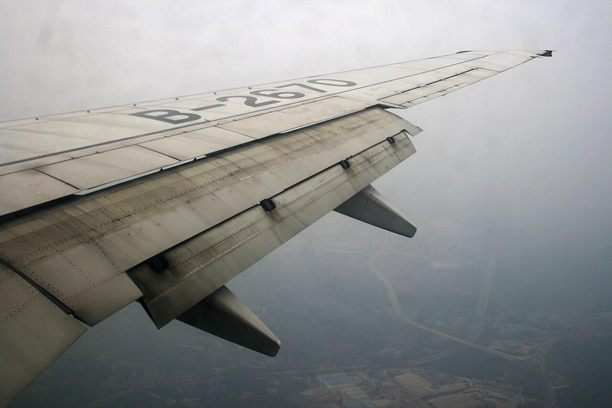
The Boeing 737's high-lift system has two parts. Trailing edge (TE) flaps run aft and down from the rear of the wing, and leading edge (LE) devices, flaps inboard and slats outboard of each engine, extend from the front. One flap lever selects both, hydraulic system B normally drives them, and an electronic unit monitors them for asymmetry, skew and uncommanded movement.
Each part also has a backup. The trailing edge flaps can be driven by an electric motor, and the leading edge devices extended by the standby hydraulic system, but this alternate operation gives up flap load relief and the trailing edge asymmetry and skew protection. The functions crews meet on the line, from flap load relief to the autoslats and the leading edge annunciator lights, are described below for the 737 NG, with the MAX differences noted. How flaps and slats raise lift is covered in high-lift devices.
High-lift system overview
The leading edge devices are four LE flaps and eight slats: on each wing, two flaps inboard of the engine and four slats outboard of it. The TE flaps have eight extended positions, 1, 2, 5, 10, 15, 25, 30 and 40. Positions 1 to 15 mainly increase lift; positions 15 to 40 increase both lift and drag. The take-off range is flaps 1 to 25, and flaps 15, 30 and 40 are the normal landing positions, flaps 15 being normally limited to airports where approach climb performance is a factor.
On the most common variants the devices are sequenced together:
| FLAP lever | TE flaps | LE flaps | Slats |
|---|---|---|---|
| UP | Up | Retracted | Retracted |
| 1, 2, 5 | Commanded position | Full extended | Extend (intermediate) |
| 10 to 40 | Commanded position | Full extended | Full extended |
Limits come from the flap placard and the limitations. The FLAPS LIMIT placard reproduced in the 737 NG FCOM gives 250 kt for flaps 1, 2 and 5, 210 kt for 10, 200 kt for 15, 190 kt for 25, 175 kt for 30 and 162 kt for 40. These figures are not common to every 737: placard speeds differ between models (the FAA Flight Standardization Board, FSB, lists revised flap placard speeds for the 737-9 against the 737-8), so the placard in the aircraft flown is the one that applies. To prevent excessive structural loads from the higher Mach number at altitude, flaps must not be extended above 20,000 ft, a memory limitation, and holding in icing conditions with any flap extended is prohibited. The wing anti-ice system protects only the three inboard slats, not the LE flaps or the outer slats.

Flap/Slat Electronics Unit
The flap/slat electronics unit (FSEU) monitors the high-lift system and carries out several of its functions:
- Flap load relief, using data from the left ADIRU, the same source as the captain's airspeed.
- Position indication of the leading edge devices, and the trailing edge needle split for asymmetry or skew.
- Asymmetry, skew and uncommanded motion protection, shutting down the drive when a fault is detected.
- Cruise protection of the leading edge devices, keeping pressure on their retract lines and depressurising the extend and full extend lines.
To stop the trailing edge flaps, the FSEU closes the trailing edge flap bypass valve, which shuts down the hydraulic drive. The same valve is closed by the ALTERNATE FLAPS master switch when the electric alternate drive is armed.
Flap lever, gates and load relief
The flap gates stop the flap lever from being moved inadvertently past two positions: position 1, to check the flap position for a one engine inoperative go-around, and position 15, for a normal go-around.
Flap load relief is armed at lever positions 30 and 40 on the most common variants:
| Lever | Retracts to | Above | Re-extends below |
|---|---|---|---|
| 40 | 30 | 163 kt | 158 kt |
| 30 | 25 | 176 kt | 171 kt |
The flap lever does not move: the flap position indicator shows the retraction and re-extension. Load relief is not available during alternate flap extension, so the placard speeds then rest entirely with the crew.
Flaps in normal operation
After take-off the flaps are retracted on a speed schedule, the bank angle being limited to 15° until V2 + 15:
| Take-off flaps | Retraction |
|---|---|
| 25 | At V2 + 15 select 15, then 5, 1 and UP as the speed reaches each flap manoeuvring speed |
| 10 or 15 | At V2 + 15 select 5, then 1 and UP |
| 5 | At V2 + 15 select 1, then UP |
| 1 | Select UP at the flaps 1 manoeuvring speed |
The green flap manoeuvring speed bugs on the speed tape mark each step; they are removed when the lever is set to 30 or 40, and the UP bug is not shown above about 20,000 ft. On an ILS approach the pilot flying calls for gear down and flaps 15 at glideslope alive and for the landing flaps at glideslope capture, with the final approach speed of VREF 30 or VREF 40 plus wind additives. On a go-around flaps 15 is normally selected, which is the reason for the gate at 15.
Flap position feeds several other systems. With the flaps at 15 or more below 19,000 ft, the engines' approach idle is selected. Beyond flaps 25 the landing gear warning horn sounds whenever the gear is not down, whatever the thrust lever position, and above flaps 10 it cannot be silenced with the horn cutout switch. The ground proximity TOO LOW, FLAPS alert warns of low terrain clearance at low speed with the flaps not in a normal landing position; the guarded FLAP INHIBIT switch on the ground proximity panel inhibits it.
Autoslat system
At flap positions 1, 2 and 5, with the slats at their intermediate position, the autoslat system moves the slats to full extend if the aeroplane approaches a stall. They start to move before the stick shaker activates and return to the extend position once the pitch attitude has been reduced sufficiently below the stall-critical attitude.
The autoslats are normally powered by system B. If a loss of pressure from the higher-volume system B engine-driven pump is sensed, the power transfer unit (PTU) supplies the volume using system A pressure, as described in B737 hydraulic system. The amber AUTO SLAT FAIL light shows a failure of the autoslat system; if it appears only during a MASTER CAUTION recall and goes out on reset, a single stall management yaw damper (SMYD) computer has failed.
Alternate flap operation
The alternate flap system is used when system B cannot drive the flaps. It has two controls:
- The guarded ALTERNATE FLAPS master switch, normally OFF. At ARM it closes the trailing edge flap bypass valve, activates the standby hydraulic pump and arms the position switch.
- The ALTERNATE FLAPS position switch. DOWN, spring-loaded to OFF, fully extends the LE devices on standby pressure when pushed momentarily, and drives the TE flaps electrically for as long as it is held. UP retracts the TE flaps electrically.
The TE flaps must be held DOWN until they reach the wanted position, and the electric drive has no asymmetry or skew protection. The LE devices, once extended by the standby system, cannot be retracted by it. The alternate flap motor has a duty cycle: 15 seconds after releasing the switch before operating it again, and 5 minutes of cooling after a complete extend and retract cycle, such as 0 to 15 and back to 0.
Exam tip: with alternate flaps the TE flaps move electrically and the LE devices extend on standby pressure but cannot be retracted. There is no flap load relief and no TE asymmetry or skew protection.
Flap and LE device indications
The flap position indicator shows the left and right TE flaps on two needles, which split for a TE asymmetry or skew. Two lights summarise the leading edge:
- LE FLAPS TRANSIT (amber): leading edge devices in transit, or a device in an improper position. It is inhibited during autoslat operation in flight.
- LE FLAPS EXT (green): at TE flaps 1, 2 and 5, all LE flaps extended and all slats in the intermediate position; at flaps 10 to 40, all LE devices fully extended.
Before taxi the take-off flaps are set and the green LE FLAPS EXT light confirmed. The LEADING EDGE DEVICES annunciator panel shows each device: no light when retracted, amber TRANSIT in transit, green EXT for LE flaps extended and slats in the intermediate position, and green FULL EXT for slats fully extended.
Uncommanded motion and asymmetry protection
An asymmetry exists when a device on one wing does not line up with its partner on the other wing. A skew happens when two symmetrical TE flap panels do not move at the same rate and twist during extension or retraction. When the FSEU detects a TE asymmetry or skew, it closes the TE flap bypass valve and the flap position indicator shows a needle split. With a wing asymmetry, the SMYDs give stall warning at a lower angle of attack and the pitch limit indications fall on both PFDs, while the minimum operating speed and the minimum manoeuvring speed (amber bar) both increase.
Uncommanded flap/slat motion detection works on both edges:
| Edge | Detected when | FSEU action |
|---|---|---|
| Leading edge | With no TE flap or autoslat command, two LE flaps, or two or more slats, move on one wing | Shuts down LE control; LE FLAPS TRANSIT lights |
| Trailing edge | With no FLAP lever or load relief command, the TE flaps move away from, or past, the commanded position, or the wrong way | Closes the TE flap bypass valve; no needle split, but the indicator disagrees with the lever |
The TE shutdown cannot be reset by the crew, who must then control the TE flaps with the alternate system. If a leading edge device is in an improper position, LE FLAPS TRANSIT stays lit and the annunciator panel shows which device is at TRANSIT, EXT, FULL EXT or retracted. The take-off configuration warning includes TE flaps outside 1 to 25, a TE skew, asymmetry or uncommanded motion, and LE devices not configured for take-off or in uncommanded motion.
Note: with hydraulic power off on the ground, the LE flaps can droop enough to give an asymmetry signal and fail the stall warning test. The remedy is to pressurise system B, retract the flaps and repeat the test.
The 737 MAX family brings two flap differences in the FSB tables: revised flap placard speeds on the 737-9 compared with the 737-8, and, in the Revision 21 draft, a revised leading edge slat extension sequence on the 737-7.

Frequently asked questions
What are the flap positions on the Boeing 737?
The flap lever has the positions UP, 1, 2, 5, 10, 15, 25, 30 and 40. Positions 1 to 15 mainly add lift and 15 to 40 add lift and drag. The take-off range is flaps 1 to 25, and flaps 15, 30 and 40 are the normal landing positions, flaps 15 normally being used where approach climb performance is limiting. Flaps must not be extended above 20,000 ft.
How does flap load relief work on the 737?
Flap load relief is a function of the flap/slat electronics unit, armed at flaps 30 and 40 on the most common variants. At flaps 40 the flaps retract to 30 above 163 kt and re-extend below 158 kt; at flaps 30 they retract to 25 above 176 kt and re-extend below 171 kt. The flap lever does not move, but the indicator shows the retraction. Load relief is not available with alternate flaps.
What is the autoslat system on the 737?
At flap positions 1, 2 and 5, when the slats are in their intermediate extend position, the autoslat function drives them to full extend as the aeroplane approaches the stall, before the stick shaker, and returns them when the pitch attitude is reduced. It is powered by system B, with the PTU supplying volume from system A if the system B engine-driven pump fails. AUTO SLAT FAIL shows a failure.
How do you extend the flaps with the alternate system on the 737?
Arm the guarded ALTERNATE FLAPS master switch, which closes the trailing edge flap bypass valve, starts the standby hydraulic pump and arms the position switch. A momentary DOWN fully extends the leading edge devices on standby pressure; holding DOWN drives the trailing edge flaps electrically until released. There is no asymmetry protection or load relief, the leading edge devices cannot be retracted, and the motor has a duty cycle.
What does the LE FLAPS TRANSIT light mean on the 737?
The amber LE FLAPS TRANSIT light shows that the leading edge devices are in transit. It stays on if the FSEU detects a device in an improper position, and it lights when the FSEU shuts down the leading edge control after detecting uncommanded motion. It is inhibited during autoslat operation in flight. The green LE FLAPS EXT light shows all devices extended.
Test yourself on B737 Flaps and Leading Edge Devices
The v1prep banks cover this topic in the B737 type-rating bank, with a worked explanation for every answer. EASA ATPL, PPL, IR and CPL, the FAA written tests and A320/B737 type ratings.
Start practising →Sources and further reading
- FAA Flight Standardization Board Report, Boeing 737, Revision 17
- EASA Type Certificate Data Sheet IM.A.120, Boeing 737
- EASA Easy Access Rules for Large Aeroplanes (CS-25), CS 25.697 to CS 25.701, lift and drag devices
- 14 CFR 25.697, Lift and drag devices, controls
- 14 CFR 25.701, Flap and slat interconnection
- FAA Aviation Maintenance Technician Handbook, Airframe (FAA-H-8083-31B)
Library articles are written for study and exam preparation. They do not replace your aircraft's approved documentation, your operator's procedures or the regulations themselves.