Combustion Chambers and Turbines
The combustion chamber and turbine form the hot section of a gas turbine engine. The chamber burns fuel continuously in compressor delivery air at almost constant pressure; the turbine expands the hot gas through nozzle guide vanes and rotor blades to drive the compressor and fan.
The combustion chamber, or combustor, and the turbine make up the hot section of a gas turbine engine. In the chamber, fuel burns continuously in the air delivered by the compressor, at almost constant pressure, so the gas leaves much hotter and with a much greater volume than it entered. In the turbine, that gas expands through rows of stationary nozzle guide vanes and rotating blades, which extract the work needed to drive the compressor and, in a turbofan, the fan. What the turbine leaves in the gas goes out through the exhaust as jet thrust.
The hot section sets the limits of the whole engine. The hotter the gas the turbine can accept, the more thrust a given core produces and the better its efficiency, but the maximum gas temperature is fixed by the materials of the nozzle guide vanes and turbine blades, not by the fuel or the compressor. Dilution air, cooled single-crystal blades and clearance control all exist to push that limit up or to protect it, and the exhaust gas temperature (EGT) the crew watches is the cockpit's window on it (see engine indications and condition monitoring).
- Combustion chamber types
- Fuel atomisation and spray nozzles
- Primary and dilution air
- Combustion stability and flame propagation
- Nozzle guide vanes and turbine stages
- Turbine blade materials and fir-tree roots
- Blade cooling and thermal barrier coatings
- Creep and the hot section
- Turbine entry temperature
- Turbine clearance control
- Frequently asked questions
Combustion chamber types
Air leaves the last compressor stage far too fast for a flame to survive, so it first passes through a diffuser, a divergent duct that slows it and raises its pressure. It then enters one of three kinds of combustion system.
- Multiple (can) chambers: separate cylindrical chambers arranged round the engine, each with its own outer casing and inner flame tube. Early jet engines used them; they are easy to develop and to maintain, but heavy and bulky for the airflow they handle.
- Tubo-annular (can-annular) chambers: individual flame tubes arranged inside one common annular casing, a compromise that makes better use of the space.
- Annular chambers: a single continuous flame tube running right round the engine between inner and outer casings. For a given airflow it is the shortest and lightest layout, and it is the one used on current airliner engines. The CFM56-5B of the A320, for example, has an annular chamber with 20 fuel nozzles and two igniters.
In a multiple-chamber system not every flame tube needs an igniter; most engines have only two. Interconnector tubes join neighbouring flame tubes, and once the lit tubes are burning, their higher pressure drives flame through the interconnectors to light the others.
Fuel atomisation and spray nozzles
Kerosene burns as a vapour, so it must enter the flame as a fine mist that evaporates at once. The fuel spray nozzle, also called the burner or fuel atomiser, does this. The simplest type forces fuel through a single fixed orifice, and it atomises well only at high pressure: the ATPL texts quote 1,500 to 2,000 psi. The engine-driven HP fuel pump turns with the HP spool through the accessory gearbox, and at the low speed of a start it cannot produce such pressures, so a plain fixed-orifice nozzle would dribble rather than spray just when good atomisation matters most. Airliner engines therefore use nozzles that atomise well across the whole range of flows, for example with two fuel passages, one sized for small flows, or airspray nozzles in which the swirling air, not the fuel pressure, breaks the fuel up.
Metered fuel reaches the nozzles through a fuel manifold round the combustion chamber (see gas turbine engine fuel system). Some engines stage the fuel between groups of nozzles. On the CFM56-5B a burner staging valve (BSV) supplies 10 of the 20 nozzles permanently and opens to the other 10 only when a high fuel-air ratio is needed, as in acceleration and at high thrust. It is closed during deceleration and at low idle, so that a small fuel flow is concentrated in fewer nozzles and burns steadily. If the fuel control system fails, a safety function supplies all 20 nozzles.
Primary and dilution air
Only part of the air entering the chamber takes part in the burning. Inside the casing, the flame tube divides the airflow into stages.
- Primary air enters at the front, through the snout and the swirl vanes round the fuel nozzle. The swirl sets up a zone of recirculating, slow-moving gas that anchors the flame. Near the centre of this primary zone the temperature reaches about 2,000 °C.
- Secondary air enters through holes in the flame tube wall and completes the combustion.
- Dilution air, also called tertiary air, enters further downstream. The ATPL texts give it as about 60% of the total flow into the chamber. It mixes with the burnt gas and brings it down to between about 1,000 and 1,500 °C, a temperature the turbine can accept.
Some of the air also flows along the inside of the flame tube wall as a cooling film, so that the metal does not melt in the flame it contains.
Combustion stability and flame propagation
A flame can survive only where the gas moves slowly enough for it to burn back against the flow, which is why the swirl and recirculation of the primary zone matter. It also burns only between a rich and a weak limit of air-fuel ratio. Plotted against the air mass flow through the chamber, these limits form the combustion stability loop. As mass flow increases, the band between the rich and weak limits narrows, until beyond a critical flow no mixture will burn and the flame blows out.
The loop explains several operating rules. A flame-out is most likely at high altitude and high airspeed, and the same conditions make a relight difficult, so after a flame-out there the crew reduces both altitude and speed to bring the chamber back inside the relight envelope, with the windmilling engine providing the airflow. The fuel control limits how quickly fuel may be added or removed, because a sudden change in fuel flow can take the mixture outside the loop or stall the compressor (see FADEC and engine fuel control). Heavy rain and ice ingestion also threaten the flame, which is why continuous ignition is selected in such conditions (see gas turbine ignition, flameout and relight).
Nozzle guide vanes and turbine stages
Leaving the chamber, the gas meets the nozzle guide vanes (NGVs), a ring of stationary aerofoils whose passages converge. In subsonic flow a convergent duct trades pressure for velocity, so the gas accelerates as its pressure falls, and the vanes turn it to strike the rotor blades at the right angle. The first-stage NGVs sit directly behind the combustion chamber and see the hottest gas in the turbine. Each turbine stage is a row of NGVs followed by a row of rotor blades on a disc.
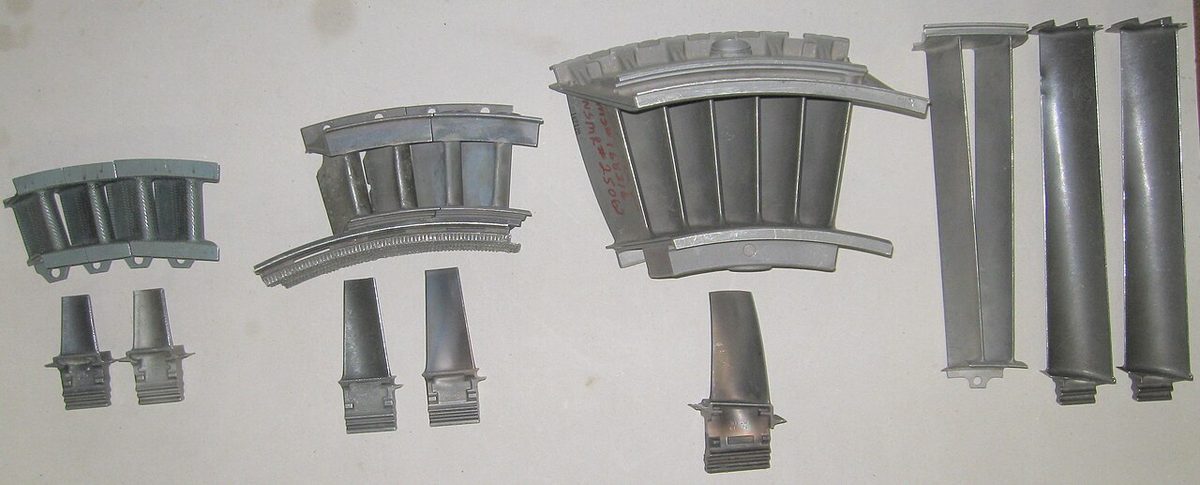
The high-pressure turbine (HPT) drives the high-pressure compressor on the HP spool (N2). The low-pressure turbine (LPT) drives the fan and low-pressure compressor on the LP spool (N1). The CFM56-5B has a single-stage HPT driving a nine-stage HP compressor, and a four-stage LPT driving the fan and a four-stage LP compressor. The CF34-10E of the Embraer 190 has the same pattern of a one-stage HPT and a four-stage LPT. Even so, the gas leaving the turbine moves faster than it did in the chamber, because the NGVs and the propelling nozzle are convergent passages that accelerate it.
Turbine blade tips travel at more than 1,500 ft per second. Blade losses fall and efficiency rises as blade speed increases, but the stresses rise with the square of that speed, so the designer is always trading one against the other. The high-bypass turbofan eases the trade: its better propulsive efficiency means that a smaller turbine can produce the same thrust.
Turbine blade materials and fir-tree roots
Turbine blades progressed from high-temperature steels to nickel-based alloys and then to superalloys, complex mixtures of nickel with chromium, cobalt, titanium, tungsten, carbon and other elements, chosen for their strength and creep resistance at high temperature. Modern engines use single-crystal turbine blades, each cast as one crystal of metal. A conventional casting is made of many grains, and the boundaries between them are where creep and cracking begin; a single-crystal blade has none.
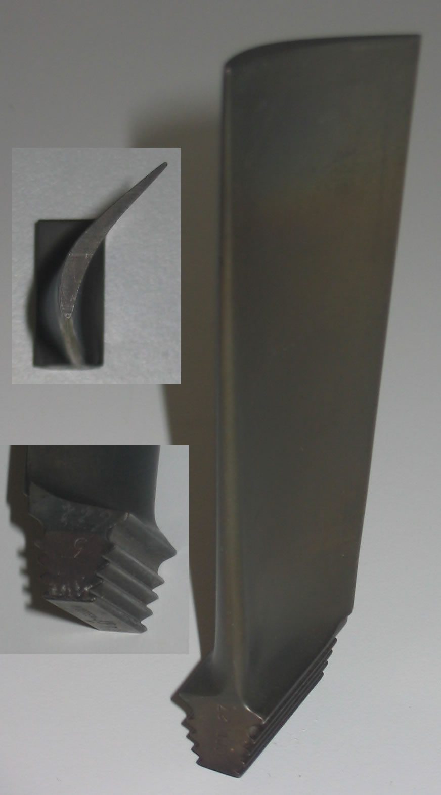
Blades are attached to the disc by a fir-tree root, a root with several pairs of lobes that fit matching serrations in the disc rim, so the centrifugal load is shared between many bearing faces. The blade is deliberately loose in its slot when the engine is at rest, which eases assembly and allows for thermal expansion; centrifugal force pulls it tight when the engine runs. Compressor blades are commonly held by a simpler dovetail root.
Blade cooling and thermal barrier coatings
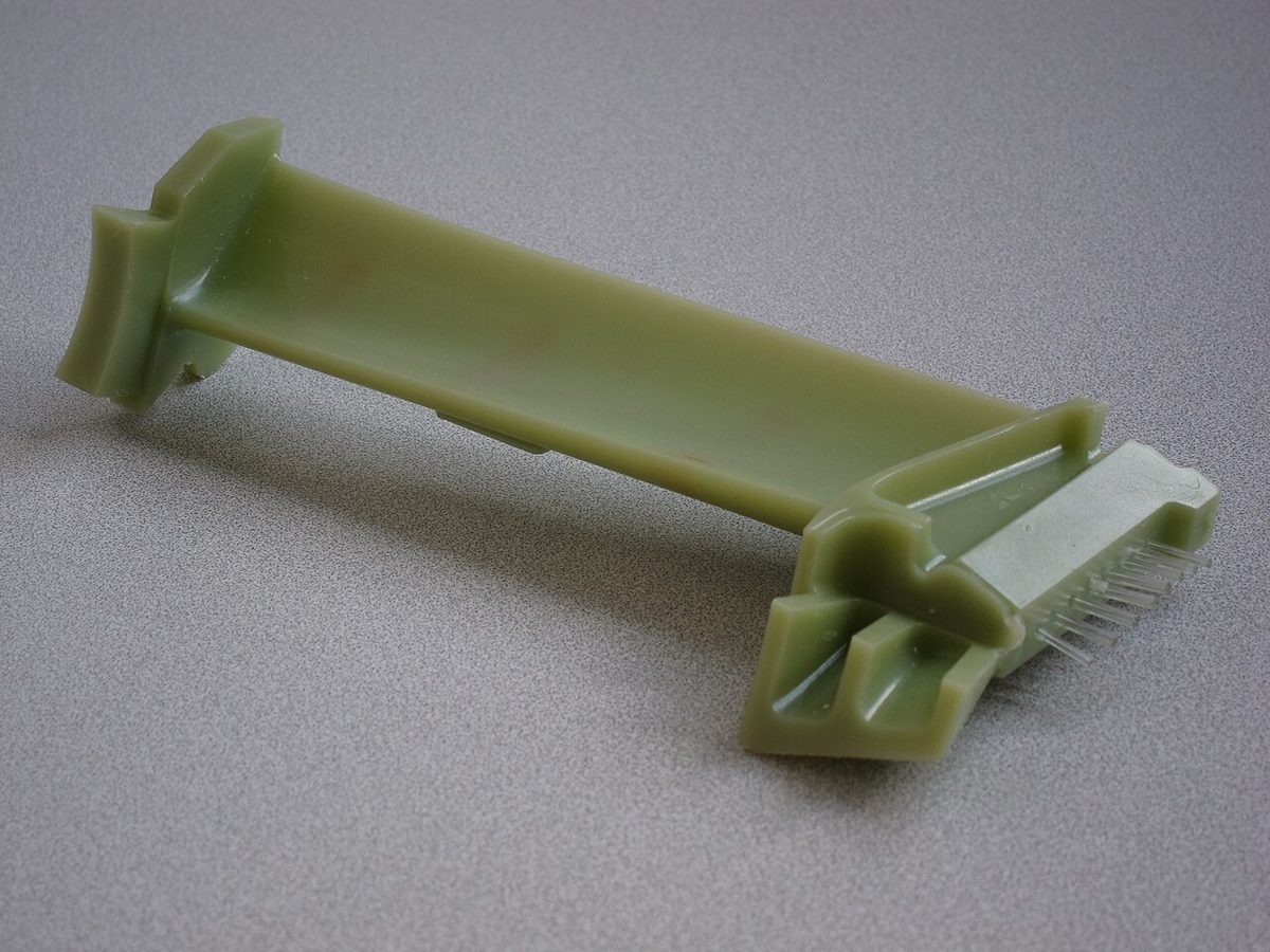
On current airline engines the gas reaching the first HP turbine stage is hotter than the melting point of the nickel alloy from which the blades are made. The blades survive because they are cooled. Turbine blade cooling uses air bled from the HP compressor, which flows through passages cast inside the blade and leaves through rows of small film cooling holes, laying a thin layer of cooler air over the surface. A thermal barrier coating (TBC), a thin ceramic layer on the blade surface, insulates the metal further. Together they keep the metal below its melting point in gas that is hotter than that.
Cooling has a price. The cooling air has been compressed, which costs work, but it does not pass through the combustion, so it reduces the efficiency of the cycle slightly.
Creep and the hot section
Creep is the slow, permanent stretching of a metal part held under stress at high temperature. A turbine blade carries a huge centrifugal load while running close to its temperature limit, so it creeps, lengthening a little over its life. Creep cannot be eliminated: even if every temperature and rpm limit is observed, it is only slowed, and every turbine blade therefore has a finite life.
Creep and oxidation increase very steeply once the metal runs hotter than its design temperature. A short over-temperature can therefore consume a disproportionate share of a blade's life, which is why exceedances are recorded and followed by a maintenance inspection. The engine hot section, the combustion chamber, NGVs and turbines, is the part of the engine most closely watched in service, through EGT trends and borescope inspections, and EGT is the parameter that most directly limits engine life, because the HP turbine blades run hottest.
Turbine entry temperature
Turbine entry temperature (TET), also called turbine inlet temperature (TIT), is the temperature of the gas entering the HP turbine, in front of the first NGVs. It is the most important limit in the design of an engine. A higher TET gives more thrust from a given core and is associated with higher thermal efficiency, together with the overall pressure ratio, but the materials of the NGVs and blades cap it.
TET is not measured directly in airline service. The gas at that point is too hot for a practical probe, so thermocouples are placed further aft, where the gas has given up some of its energy, and their reading is used as an index of the temperature upstream. Depending on the station and the manufacturer this is called EGT, turbine gas temperature (TGT) or inter-turbine temperature (ITT). Because the probe position differs, the limits are not comparable between engines: the CFM56-5B take-off EGT limit is 950 °C and the V2500-A5's is 635 °C, and the lower figure does not mean a cooler core.
The temperature limit also shapes engine ratings. A flat-rated engine delivers its full rated thrust from very cold days up to a flat-rate temperature; above it, the temperature limit takes over and the available thrust falls as the outside air gets warmer (see gas turbine principles, thrust and ratings).
Turbine clearance control
The gap between the turbine blade tips and the casing is a leak: gas that flows over the tips does no work. The gap does not stay constant, because the casing, the discs and the blades heat and cool at different rates, and the blades stretch under centrifugal load. Active clearance control manages it by cooling the turbine casing so that it shrinks towards the blade tips.
On the CFM56-5B, fan discharge air, modulated by FADEC-controlled valves, is blown onto the turbine casings. HP turbine clearance control (HPTCC) acts on the HP turbine case and LP turbine clearance control (LPTCC) on the LP turbine case; fan air is cool enough for both, the LP turbine running much cooler than the HP turbine. With a valve closed no cooling air reaches the casing, the casing runs hot and the clearance is at its maximum. Opening the valve cools and shrinks the casing, closing the gap, which improves turbine efficiency and specific fuel consumption and lowers EGT. The clearance must never close so far that the blade tips rub the casing, which is why it is scheduled by the engine control according to the operating condition rather than simply held at a minimum.
Frequently asked questions
What are the three types of gas turbine combustion chamber?
Multiple or can chambers are separate cylindrical chambers arranged round the engine, each with its own casing and flame tube, joined by interconnector tubes. Tubo-annular or can-annular chambers place individual flame tubes inside one common annular casing. Annular chambers use a single continuous flame tube round the engine, the shortest and lightest layout, and the one used on current airliner engines such as the CFM56-5B, whose annular chamber has 20 fuel nozzles and two igniters.
Why is most of the air in a combustion chamber not used for burning?
The flame burns only where air and fuel are close to the right proportions, and at the centre of the primary zone the gas reaches about 2,000 °C, far hotter than turbine materials can take. The rest of the air, about 60 per cent of the total in the ATPL texts, is added downstream as dilution air. It cools and mixes the gas down to between about 1,000 and 1,500 °C before it reaches the nozzle guide vanes.
What is creep in a turbine blade?
Creep is the slow, permanent stretching of a metal part that carries a high load at high temperature. A turbine blade is pulled outward by enormous centrifugal force while running close to its temperature limit, so it lengthens a little over its life. Creep cannot be avoided, even if every rpm and temperature limit is respected; careful operation only slows it. Every turbine blade therefore has a finite life, and over-temperatures consume it quickly.
Why are turbine blades fitted with fir-tree roots?
A fir-tree root has several pairs of lobes that fit matching serrations in the disc rim, so the very large centrifugal load of the blade is shared between many bearing faces. The blade is deliberately left slightly loose in the disc when the engine is at rest, which eases assembly and allows for thermal expansion. When the engine runs, centrifugal force pulls it tight. Compressor blades usually use a simpler dovetail root.
What is the difference between turbine entry temperature and EGT?
Turbine entry temperature is the temperature of the gas as it enters the high-pressure turbine, the hottest point the turbine sees and the true limit of the engine. It is not measured in service. EGT is measured further aft, after the gas has given up energy in the turbine, and is used as an index of what is happening upstream. Because the probe position differs between engines, EGT limits differ: the take-off limit is 950 °C on the CFM56-5B and 635 °C on the V2500-A5.
What does turbine clearance control do?
It keeps the gap between the turbine blade tips and the casing small, because gas leaking over the tips does no work. On the CFM56-5B the FADEC modulates cool fan air onto the HP and LP turbine casings, which shrink onto the blades. With the valve closed the casing runs hot and the clearance is at its largest; opening it closes the gap, improving turbine efficiency and fuel consumption and lowering EGT.
Test yourself on Combustion Chambers and Turbines
The v1prep banks cover this topic in Aircraft General Knowledge (021), with a worked explanation for every answer. EASA ATPL, PPL, IR and CPL, the FAA written tests and A320/B737 type ratings.
Start practising →Sources and further reading
Library articles are written for study and exam preparation. They do not replace your aircraft's approved documentation, your operator's procedures or the regulations themselves.