Gas Turbine Intakes and Compressors
The intake and compressor supply the combustion chamber with air at high pressure. The intake slows the air and delivers it evenly to the compressor face; the compressor, centrifugal or axial, raises its pressure in stages. If the airflow over the compressor blades breaks down, the compressor stalls or surges.
The intake and the compressor are the front end of a gas turbine. The intake brings air from outside to the compressor face, slowing it and spreading it evenly; the compressor raises its pressure many times before it reaches the combustion chamber. Together they decide how much air the engine can use, and therefore how much thrust it can make and how efficiently.
The compressor is also the most delicate part of the engine aerodynamically. Its blades are small aerofoils, and like a wing they stall if the air meets them at too great an angle. A compressor stall can grow into a surge, a violent breakdown of the airflow through the whole engine. Most of the variable geometry in a modern engine, and several of the pilot's handling rules, exist to prevent it.
Engine intakes
A subsonic airliner intake is a short pitot-type duct that diverges towards the engine. In flight a divergent duct slows the air and raises its pressure, so the intake delivers air to the fan at a lower speed than the aircraft's and turns part of the air's kinetic energy into pressure: the ram effect described in gas turbine principles, thrust and ratings. On the ground the reverse happens. The engine must accelerate still air into the intake, and the pressure at the compressor face falls below ambient.
The intake must deliver the air with as little pressure loss and as little distortion, uneven pressure or swirl across the face, as possible, at every speed, angle of attack and crosswind the aircraft meets. Its rounded lip is protected by the engine anti-ice system, which heats it from inside with hot bleed air; on the A320 each engine's nacelle anti-ice uses air from its own HP compressor. Ice that forms on the lip and sheds can damage the fan and cause a stall, which is why engine anti-ice is selected early in icing conditions (see thermal anti-icing).
An intake is also a vacuum cleaner. Engine power is kept low during start, taxi and reverse thrust to avoid drawing debris off the ground, and intake and exhaust covers are fitted after flight to keep contaminants out and to stop the engine windmilling, which would turn it without lubrication. The hazards of birds and debris are covered in bird strike and foreign object damage.
On some rear-engined airliners the centre engine, in the tail, is fed through an S-duct intake from an opening at the base of the fin. The air must turn through two bends, and in a crosswind or with a disturbed inflow it can reach the compressor unevenly. A rolling take-off, in which thrust is set progressively as the aircraft moves, lets the flow through the intake settle and reduces the risk of a stall or surge. The same technique is used on underwing engines; see take-off procedures and rejected take-off.
Centrifugal compressors
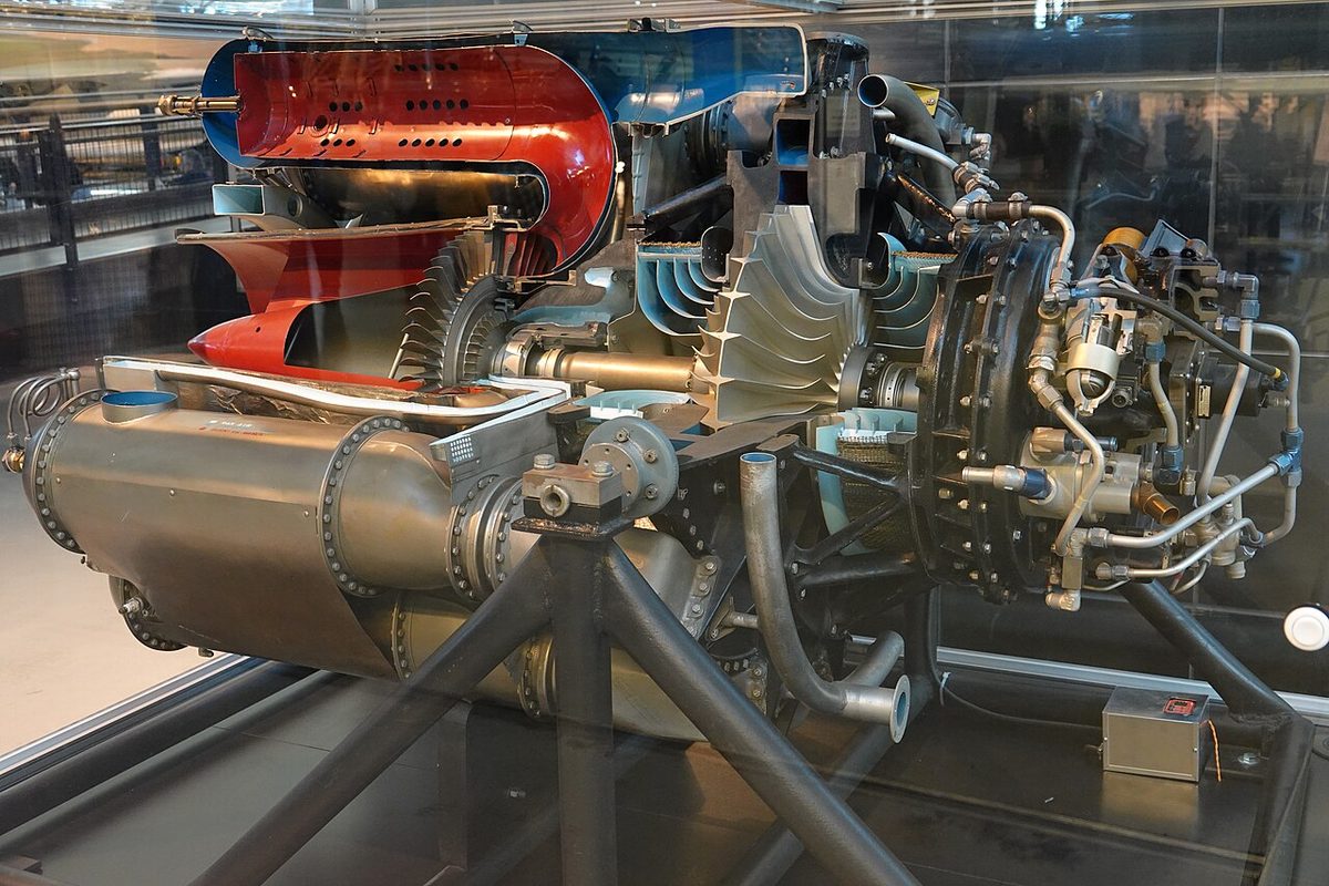
A centrifugal compressor has an impeller, a disc with radial vanes, that draws air in near its centre and flings it outwards at high speed. The air then passes through a ring of diffuser vanes, divergent passages that slow it and turn its velocity into pressure, and into a manifold that leads it to the combustion chambers. A single centrifugal stage gives a large pressure rise, and the design is simple and robust. Its drawbacks are a large diameter for the airflow it handles and the difficulty of adding more stages.
Many early jet engines used centrifugal compressors. Today they are found mainly in small gas turbines, such as auxiliary power units, helicopter engines and small turboprops, sometimes as the last stage behind a few axial stages.
Axial compressors and spools
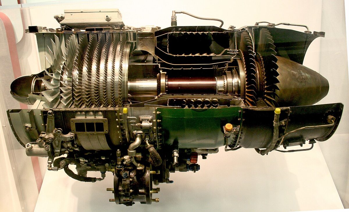
An axial compressor moves the air parallel to the shaft through alternating rows of rotating rotor blades and stationary stator vanes. A rotor row and the stator row behind it form a stage. The rotor blades do work on the air, raising its velocity and pressure; the stator vanes slow it, turning velocity into pressure, and turn it to meet the next rotor row at the right angle. The axial velocity through the compressor is kept roughly constant, so the annulus narrows towards the rear as the air is compressed. Each stage gives only a small rise in pressure, and a large pressure ratio needs many stages. The temperature rises with every stage, by several hundred degrees in all.
Modern engines split the axial compressor between spools. The low-pressure compressor (LPC), or booster, turns with the fan on the LP spool (N1); the high-pressure compressor (HPC) turns with the HP turbine on the HP spool (N2). The CFM56-5B of the A320 has a 4-stage LPC and a 9-stage HPC, the IAE V2500-A5 a 4-stage LPC and a 10-stage HPC. The arrangement of spools is described in gas turbine engine types.
The compressor is also the source of bleed air for the aircraft. On a CFM56-powered A320 it is normally taken from the 5th, intermediate-pressure, stage of the HPC, and from the 9th stage through the HP valve when the engine runs at low power and the lower stage cannot give enough pressure; the V2500 uses its 7th and 10th stages (see bleed air and pneumatic systems).
Pressure ratio and diffusers
The compressor pressure ratio is the pressure at a compressor's outlet divided by the pressure at its inlet. The overall pressure ratio (OPR) compares the delivery pressure of the last compressor stage with the pressure at the engine inlet, and so includes the fan and every compressor. The CFM56-5B has an OPR of about 32:1 and the V2500-A5 a very similar figure, about 31.5:1. In flight the ram compression of the intake adds to it.
A higher pressure ratio raises thermal efficiency and lowers specific fuel consumption, which is why it has risen steadily. It is limited by the temperature of the compressor delivery air, by the number of stages needed and by the difficulty of keeping so many stages stable across the whole range of engine speed.
Between the last compressor stage and the combustion chamber the air passes through a diffuser, a divergent duct that slows it so that a flame can survive in the chamber. The static pressure there is the highest anywhere in the engine (see combustion chambers and turbines).
Compressor stall and surge
The angle at which the air meets a rotor blade depends on two velocities: the axial velocity of the air coming towards the blade and the blade's own rotational speed. If the axial velocity falls too far for the blade speed, the angle of attack becomes excessive and the flow separates from the blade: a compressor stall. A stall may affect only a few blades or stages.
A compressor surge is a complete breakdown of the flow through the compressor. The compressor can no longer hold the pressure behind it, and the high-pressure air flows back towards the front; in a severe surge the gas flow reverses through the intake. The terms engine surge and compressor stall are often used loosely for one another.
Causes include:
- excessive fuel flow, typically in too rapid an acceleration, which raises the back-pressure from the combustion chamber and reduces the axial velocity; the ATPL texts give fuel system malfunction or mishandling as the most common cause of surge;
- disturbed intake flow, from crosswinds or tailwinds on the ground, high angles of attack, S-duct intakes or severe turbulence;
- damaged or contaminated blades, from foreign objects, birds, erosion or dirt, which reduce the compression ratio;
- ingestion of ice or volcanic ash.
The signs are a loud bang or series of bangs, a rise in EGT, because less air is left to cool the same fuel flow, and increased vibration, often with fluctuating N1 and a loss of thrust that can make the aircraft yaw. A severe surge can bend rotor blades enough for them to strike the stator vanes, with serious damage.
The ATPL answer is to close the thrust lever slowly, so that the fuel flow falls back into step with the airflow. Type procedures say the same in their own words: the Boeing 737 recall items for engine limit, surge or stall disengage the autothrottle and retard the thrust lever until the indications stabilise or the lever is closed. The engine indications identify which engine is at fault. At Kegworth in 1989 the fan of a Boeing 737-400's left engine was damaged and the engine surged, with heavy vibration, noise and shuddering; the crew shut down the healthy right engine (see engine failure and engine fire).
Compressor bleed valves
At low rotational speed the stages of a long compressor are mismatched. The rear stages cannot pass all the air the front stages deliver, the flow through the front stages slows, and their blades meet the air at too great an angle. A compressor bleed valve part way along the compressor lets the surplus air out, keeping the front stages flowing fast enough. Such valves open at low speed, during starting and in rapid thrust changes, and close as the engine accelerates.
On the CFM56-5B the variable bleed valves (VBV) dump air from the exit of the LP compressor into the fan duct at low power and during acceleration and deceleration, preventing booster stall when the HP compressor cannot take all the air offered. Their opening and closing can be heard as the thrust changes. These handling bleeds are separate from the customer bleed that feeds the pneumatic system.
Inlet guide vanes and variable stators
Inlet guide vanes (IGV) are a row of stationary vanes ahead of the first rotor stage that direct the air onto it at the right angle. Variable inlet guide vanes (VIGV) can be turned: at low compressor speed they are set to give the air the greatest swirl, which reduces the angle at which it meets the first rotor blades.
Variable stator vanes (VSV) extend the same idea to the first few stator rows of the HP compressor. As compressor speed falls below its design value they close progressively, preserving the angle of attack of the following rotor stages. On the CFM56-5B the VSVs are fully closed for engine start, open progressively with N2 and are fully open at high thrust; the FADEC schedules them, together with the VBVs, against N2 and ambient conditions through the hydromechanical unit (see FADEC and engine fuel control).
Two further design choices widen the stall-free range. A multi-spool compressor lets each part turn at its own speed; when the thrust is reduced the LP spool slows faster than the HP spool, keeping the angle of attack of its blades in step. The ATPL texts also list active clearance control, which controls the gap between the blade tips and the casing; on the CFM56-5B it cools the turbine casings with fan air to improve fuel consumption, and compressor stall margin is left to the VBVs and VSVs. Together with bleed valves and variable vanes these are the standard answers to the exam question on how compressor stall and surge are prevented.
Part-span shrouds
Long, thin fan blades are prone to vibration. A part-span shroud, also called a snubber, is a small platform part way along each blade that bears against those of the neighbouring blades when the fan turns, forming a ring that stiffens the whole row. The price is a little weight and an obstruction in the airflow. The CFM56-5B has 36 titanium fan blades with part-span shrouds; the V2500-A5 has 22 wide-chord blades that are stiff enough to do without them and resist foreign object damage better.
Fan blade vibration is watched through the N1 vibration indication (see engine indications and condition monitoring). The Kegworth fan blade failed by fatigue, the AAIB found, after vibratory stress from a fan vibration mode excited at high corrected fan speed at altitude, which engine certification testing had not revealed.
Frequently asked questions
What is the difference between a compressor stall and a surge?
A compressor stall is a breakdown of the airflow over some of the compressor blades, which meet the air at too high an angle of attack, like a stalled wing. It may affect only a few blades or stages. A surge is a complete breakdown of the flow through the compressor: the pressurised air behind it flows back, in a severe case out through the intake with a loud bang, and the engine loses thrust while EGT rises.
What causes a jet engine compressor to stall?
Anything that upsets the relationship between the speed of the air entering each stage and the speed of the blades. The ATPL texts name excessive fuel flow during acceleration, which raises the back-pressure from the combustion chamber, as the most common cause. Others are disturbed intake airflow in crosswinds, at high angles of attack or from S-duct intakes, damaged or contaminated blades, ice or bird ingestion, and operation away from the design speed without bleed valves or variable vanes.
What are the indications of a compressor surge?
A loud bang or series of bangs, a rise in exhaust gas temperature, because less air is left to cool the same fuel flow, and increased vibration. Thrust is lost on the affected engine, which can make the aircraft yaw, and N1 may fluctuate. Passengers or cabin crew may see flames from the engine. The ATPL answer for the pilot's action is to close the thrust lever slowly on the affected engine.
What do variable stator vanes do?
Variable stator vanes are the inlet guide vanes and first stator rows of a compressor, mounted so that their angle can be changed. At low rotational speed they are closed, so that the air meets the following rotor blades at a suitable angle; as speed rises they open. On the CFM56-5B the FADEC schedules them against N2 through the hydromechanical unit: fully closed for start, fully open at high thrust.
What is a variable bleed valve on a turbofan?
A variable bleed valve (VBV) lets air out of the compressor when the stages would otherwise be mismatched. On the CFM56-5B the VBVs open at low power and during rapid thrust changes to dump air from the exit of the low-pressure compressor into the fan duct, so that the booster stages do not stall when the high-pressure compressor cannot swallow all the air they deliver. The FADEC schedules them against N2 and ambient conditions.
Test yourself on Gas Turbine Intakes and Compressors
The v1prep banks cover this topic in Aircraft General Knowledge (021), with a worked explanation for every answer. EASA ATPL, PPL, IR and CPL, the FAA written tests and A320/B737 type ratings.
Start practising →Sources and further reading
- FAA Aviation Maintenance Technician Handbook, Powerplant (FAA-H-8083-32B), Chapter 1, Aircraft Engines
- EASA, Explanatory Note to ED Decision 2018/001/R, Part-FCL theoretical knowledge learning objectives (021 Powerplant)
- EASA Easy Access Rules for Engines (CS-E)
- 14 CFR Part 33, Airworthiness Standards, Aircraft Engines
- FAA Airplane Flying Handbook (FAA-H-8083-3C), Transition to Jet-Powered Airplanes
- AAIB Aircraft Accident Report 4/90, Boeing 737-400 G-OBME, near Kegworth, 8 January 1989
Library articles are written for study and exam preparation. They do not replace your aircraft's approved documentation, your operator's procedures or the regulations themselves.