B737 Fuel System
The Boeing 737 fuel system stores fuel in two wing main tanks and a centre tank, each with two AC-powered pumps, and feeds the engines and the APU, using the centre tank first because its pumps deliver at a higher pressure than the main tank pumps.
The Boeing 737 carries its fuel in three tanks and feeds the two engines and the APU from them with six electric pumps. Much of the system is left to the crew: the centre tank pumps are switched on and off by hand, and the crossfeed is a manual selector. What happens automatically is limited: the centre tank empties first because its pumps push harder, a centre pump that loses pressure shuts itself off, and a jet pump recovers the last of the centre fuel.
This article follows the 737 Next Generation (NG) flight crew operations manual (FCOM), with its kilogram figures, and notes where the 737 MAX differs. The general principles are in fuel feed, boost pumps and crossfeed, and the Airbus approach in the A320 fuel system.
Tanks and fuel pumps
Main tanks No. 1 and No. 2 are integral with the wing structure. The centre tank lies between the wing roots, within the fuselage area, and extends out into the wing. The NG FCOM gives the usable capacities at a level attitude; the MAX figures are the fuel capacities of the 737-8, -9 and -8200 in the EASA type certificate data sheet (TCDS):
| Tank | 737 NG, FCOM | 737 NG mass at 0.8029 kg/L | 737-8, -9, -8200, EASA TCDS |
|---|---|---|---|
| Main tank No. 1 | 4,876 L | 3,915 kg | 4,819 L |
| Main tank No. 2 | 4,876 L | 3,915 kg | 4,819 L |
| Centre tank | 16,273 L | 13,066 kg | 16,179 L |
| Total | 26,025 L | 20,896 kg | 25,817 L |
The two columns come from different documents. For a like-for-like comparison, the same TCDS gives the 737-800 a total of 26,024 L, one litre less than the FCOM's 26,025 L.
Each tank has two AC-powered fuel pumps, cooled and lubricated by the fuel passing through them: forward and aft pumps in each main tank, left and right pumps in the centre tank. Check valves throughout the system keep the fuel flowing in the right direction and prevent fuel from transferring between tanks. One temperature sensor, in main tank No. 1, drives the FUEL TEMP indicator on the fuel panel, which uses AC power. The tank fuel temperature must not exceed 49 °C, and must be at least −43 °C or 3 °C above the freezing point of the fuel, whichever is higher, before take-off and in flight; a fuel system icing inhibitor does not change that minimum.
Each main tank fuel pump LOW PRESSURE light comes on amber when its pump's output pressure is low or its FUEL PUMP switch is OFF. Two lights in the same tank bring on the MASTER CAUTION and FUEL annunciator; a single one does so only on a master caution recall. The lights may flicker when a tank is low and the aeroplane is climbing, descending or standing nose-down on the ground.
On variants fitted with a nitrogen generation system (NGS), bleed air is converted into nitrogen-enriched air that reduces the flammability of the centre tank (see fuel tanks, venting and inerting). It runs automatically, with no flight deck indication, and may be inoperative for dispatch under the MEL.
Centre tank operation and auto shutoff
The centre tank fuel pumps produce a higher pressure than the main tank pumps. With every pump running, the centre tank therefore feeds both engines until its quantity is close to zero, and the engines are then fed from their own main tanks. This centre tank fuel usage is a matter of pressure, not of valves or sequencing logic.
The loading rule matches it: main tanks 1 and 2 must be full if the centre tank contains more than 453 kg. The centre pumps, in turn, are switched on only if the centre tank holds more than 453 kg, and never with the flight deck unattended. In the before start procedure both are selected ON, and their LOW PRESSURE lights should illuminate momentarily and go out; a light that stays on means that pump is switched off again.
The centre tank fuel pump auto shutoff works pump by pump: when a pump's sensor detects low output pressure, that pump shuts off after a short delay. Setting its switch to OFF resets the logic, and ON again runs the pump until the switch goes OFF or the logic stops it once more.
The amber centre tank LOW PRESSURE lights come on only when output pressure is low and the switch is ON. One light lit continuously for 10 seconds brings on MASTER CAUTION and the FUEL annunciator. In cruise with little centre fuel left, the lights may flicker, sometimes after the centre quantity already reads zero, for as long as 5 minutes before the caution appears.
Exam tip: with the switches OFF on the preflight check, the centre tank LOW PRESSURE lights are out but the main tank LOW PRESSURE lights are on. A centre light needs the switch ON; a main tank light also comes on with the switch OFF.
In the climb, the crew switch off a centre pump whose LOW PRESSURE light comes on, and both if the centre tank is empty. Once in level flight with usable centre fuel, a pump switched off in the climb is selected ON again. The limitations prohibit intentionally running a centre tank pump dry, with its LOW PRESSURE light on, on the ground or in flight.
Scavenge jet pump
The centre tank fuel scavenge jet pump moves whatever fuel is left in the centre tank into main tank No. 1. It works automatically whenever the main tank No. 1 FWD pump switch is ON. The transfer begins when main tank No. 1 is down to about half, and once scavenging has started it continues for the rest of the flight.
Suction feed and crossfeed
When the pump pressure in a main tank is low, each engine can draw fuel from its own main tank through a suction feed line that bypasses the pumps. The limitation is altitude. As the aeroplane climbs, the lower air pressure releases dissolved air from the fuel, and this air can collect in the suction line and restrict the flow; at high altitude, thrust deterioration or flameout may follow. Once the dissolved air has been depleted at cruise altitude, which takes a time depending on altitude, fuel temperature and fuel type, the engine may be capable of suction feed at cruise power.
The APU is fed from the left side of the fuel manifold when the AC pumps are running; without them it is suction fed from main tank No. 1.
The crossfeed valve joins the No. 1 and No. 2 engine feed lines. It is driven by a DC motor from the battery bus and controlled by the CROSSFEED selector. With it open, a main tank with operating pumps can supply both engines, and continued crossfeed use produces a progressive imbalance. Its blue VALVE OPEN light is bright while the valve is in transit or disagrees with the selector, dim when the valve is open and out when it is closed.
On battery power alone, with all generators lost, the crossfeed valve, the engine and spar fuel shutoff valves with their lights, and the fuel quantity indicators still work. The AC fuel pumps are not on that list.
Engine and spar shutoff valves
Fuel reaches each engine through two valves in series, and flows only when both are open:
- The spar fuel shutoff valve, in the wing leading edge outboard of the pylon at the engine mounting station, is driven by a DC motor from the hot battery bus.
- The engine fuel shutoff valve, on the engine, is fuel actuated and solenoid controlled, powered from the battery bus.
Moving the engine start lever to IDLE opens both valves electrically, the engine valve through the EEC; moving it to CUTOFF, or pulling the engine fire switch, closes both. Downstream, the first stage of the engine fuel pump raises the pressure, two fuel/oil heat exchangers warm the fuel with IDG and engine oil, and a filter removes contaminants. If the filter becomes saturated the fuel bypasses it, and the amber FILTER BYPASS light warns of the impending bypass first.
The ENG VALVE CLOSED and SPAR VALVE CLOSED lights follow Boeing's valve transit light convention:
| Blue light | Meaning |
|---|---|
| Bright | Valve in transit, or its position disagrees with the start lever or engine fire switch |
| Dim | Valve closed |
| Off | Valve open |
A light that stays bright after a start lever movement therefore signals a valve that has not followed its command.
Fuel quantity, alerts and imbalance
The usable fuel in each tank is shown in white on the centre upper display unit, with AC or DC power. Each tank figure may be up to 2.0 % high or low on the ground and 2.5 % in flight. To check the gauges on the ground, six fuel measuring sticks in each main tank and four in the centre tank are withdrawn until they latch magnetically to an internal float, and the depth is read where the stick passes through the wing skin.
Three amber alerts accompany the gauges:
| Alert | Displayed when | Removed when |
|---|---|---|
| LOW | A main tank holds less than 907 kg; that tank's arc and digits turn amber | The tank holds 1,134 kg again |
| CONFIG | Either engine running, centre tank above 726 kg and both centre tank pump switches OFF; the centre arc and digits turn amber | Both engines stopped, centre tank below 363 kg, or one centre pump switch ON |
| IMBAL | Main tanks differ by more than 453 kg, on the ground or in the air; shown below the lighter tank | Imbalance reduced to 91 kg |
When the LOW and IMBAL alerts would both be shown, the LOW alert inhibits the imbalance alert. The fuel imbalance limit behind the IMBAL alert is a limitation: any scheduled imbalance between main tanks 1 and 2 must be zero, and a random imbalance must not exceed 453 kg for taxi, take-off, flight or landing.
Fuel flow indication
Each engine's fuel flow (FF) readout is measured after the fuel has passed the engine fuel shutoff valve and is shown in kilograms per hour × 1000. The FUEL FLOW switch on the engine display control panel is spring-loaded to RATE:
- RATE: fuel flow.
- USED: fuel used since the last reset; after 10 seconds the display reverts to fuel flow.
- RESET: sets fuel used to zero. Fuel used is shown for 1 second, counts down to zero, and the display returns to fuel flow.
On the preflight the switch is moved to RESET and then RATE. During an engine start the fuel flow indication lags the actual flow by about two seconds, so EGT may start to rise before any fuel flow is shown.
Refuelling and defuelling
Rapid fuelling and defuelling are done at the single point pressure fuelling station in the right wing, whose hose receptacle is in the right wing leading edge. The station is also used to transfer fuel between tanks on the ground, and each tank has its own quantity indicator there.
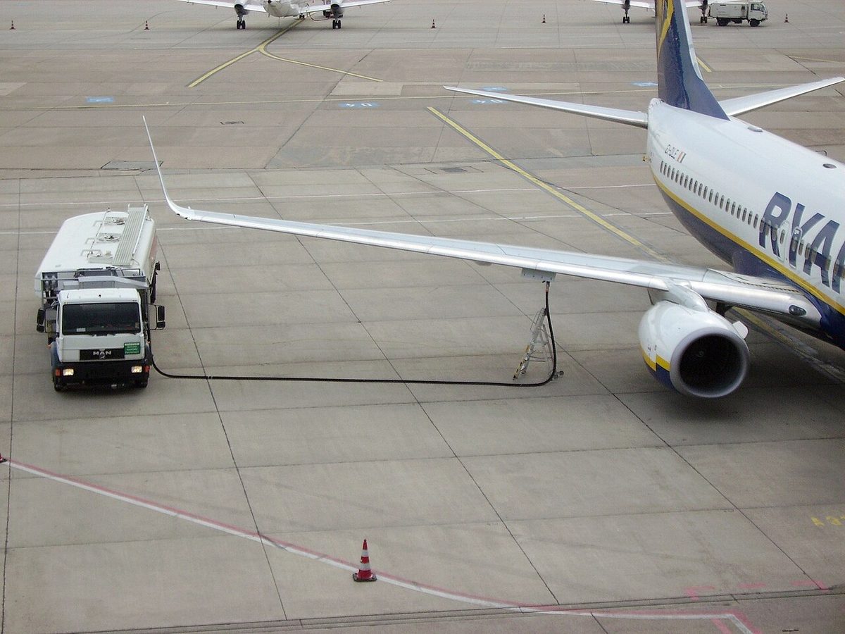
The refuelling power control relay uses a proximity sensor at the fuelling door: with the door closed the fuelling system is unpowered, and opening the door powers it. If the relay fails, the FUEL DOOR SWITCH BYPASS position of the fuelling indication test switch energises the panel. With the battery switch ON and the door open, fuel pressure opens each tank's fuelling valve; a solenoid override can open a valve mechanically. A tank's blue VALVE POSITION light shows while its valve switch is OPEN and the tank is not full, and a shutoff system closes the valve automatically when the tank is full.
The manual defuelling valve, outboard of engine No. 2, connects the engine feed system to the fuelling station. It is opened for defuelling and for tank-to-tank transfers; closed, it isolates the feed system from the station. As a memory limitation, the HF radios are not operated during refuelling: keying an HF transmitter while fuel is being loaded can injure people or start a fire (see refuelling safety and fuel emergencies).
737 NG and 737 MAX
The 737 MAX holds slightly less fuel: the EASA TCDS gives the 737-8, -9 and -8200 a total of 25,817 L (6,820 US gal), against 26,024 L (6,875 US gal) for the 737-800. For the MAX, the same TCDS prohibits any wide-cut fuel, such as Jet B or JP-4, and fuel containing Kathon FP1.5 biocide with the LEAP-1B engines. The tank temperature limits are the same on both. The MAX Display System uses four large screens instead of the NG's six display units, so the display layout differs. The thresholds in this article are those of the NG FCOM; MAX crews take theirs from the MAX FCOM.
Frequently asked questions
Why does the Boeing 737 use centre tank fuel first?
Because the centre tank pumps produce a higher pressure than the main tank pumps. Although all six pumps run, both engines are therefore fed from the centre tank until it is almost empty, and only then from their own main tanks. A related loading rule requires main tanks 1 and 2 to be full whenever the centre tank holds more than 453 kg.
What is the fuel imbalance limit on the Boeing 737?
The 737 NG limitations require any scheduled imbalance between main tanks 1 and 2 to be zero, and a random imbalance must not exceed 453 kg for taxi, take-off, flight or landing. The amber IMBAL alert appears below the lighter tank when the main tanks differ by more than 453 kg, on the ground or in the air, and stays until the difference is back down to 91 kg.
What does the fuel CONFIG alert mean on the 737?
It warns that centre tank fuel is not being used. The amber CONFIG alert appears when either engine is running, the centre tank holds more than 726 kg and both centre tank pump switches are OFF. It stays until both engines are stopped, the centre tank holds less than 363 kg or one centre tank pump switch is selected ON.
When does the fuel LOW alert appear on the Boeing 737?
The amber LOW alert appears when a main tank holds less than 907 kg, and the quantity arc and digits of that tank turn amber. It stays displayed until the tank is refilled to 1,134 kg. When LOW and IMBAL would both be shown, the LOW alert inhibits the imbalance alert.
What is suction feed on the Boeing 737?
If the pump pressure in a main tank is low, the engine can still draw fuel from its own main tank through a suction feed line that bypasses the pumps. Dissolved air released during the climb can collect in that line, and at high altitude thrust deterioration or a flameout may follow. Once the air has been depleted at cruise altitude, the engine may run on suction feed at cruise power.
What does the scavenge jet pump do on the 737?
It recovers the fuel left in the centre tank. With the main tank No. 1 forward pump switch ON, the scavenge jet pump automatically transfers any remaining centre tank fuel into main tank No. 1. The transfer starts when main tank No. 1 is down to about half and, once started, continues for the rest of the flight.
Test yourself on B737 Fuel System
The v1prep banks cover this topic in the B737 type-rating bank, with a worked explanation for every answer. EASA ATPL, PPL, IR and CPL, the FAA written tests and A320/B737 type ratings.
Start practising →Sources and further reading
- EASA Type Certificate Data Sheet IM.A.120, Boeing 737
- FAA Flight Standardization Board Report, Boeing 737
- EASA Easy Access Rules for Large Aeroplanes (CS-25), CS 25.951 to CS 25.1001, fuel system
- 14 CFR 25.981, Fuel tank explosion prevention
- FAA Aviation Maintenance Technician Handbook, Airframe (FAA-H-8083-31B), Chapter 14, Aircraft Fuel System
Library articles are written for study and exam preparation. They do not replace your aircraft's approved documentation, your operator's procedures or the regulations themselves.