A320 Fuel System
The A320 fuel system stores fuel in an inner and an outer tank in each wing, a centre tank and optional additional centre tanks, feeds the engines and APU through six main pumps in a fixed sequence, cools the generators with recirculated fuel and measures the quantity on board.
The A320 fuel system is largely automatic. Pumps, valves and sensors use the fuel in a set order without crew action: centre tank first, then the inner wing tanks, with the outer wing fuel kept until last. Besides feeding the engines and the APU, the system cools the electrical generators, keeps fuel in the outer wing for structural reasons and controls the refuelling.
For the crew the interest lies in the logic: why the centre tank empties first although every pump is running, what the MODE SEL pushbutton changes, when the outer tank fuel moves and which alerts mean that fuel has become unusable. The figures below are those of the A320 as described in the FCOM. The A321's fuel system works differently, and fuel is the only item of the FAA Flight Standardization Board's A320-to-A321 differences table flagged as a procedural change. General principles are in fuel feed, boost pumps and crossfeed and fuel tanks, venting and inerting.
Tanks and venting
Each wing contains an inner tank and an outer tank, and the centre tank lies between the two wings. One or two additional centre tanks (ACTs) may be installed. Outboard of each outer tank, a vent surge tank vents the system and catches any spillage. Filled to maximum capacity, the fuel can expand by 2 %, about a 20 °C temperature rise, without spilling. Overpressure protectors are fitted in each vent, in each inner and outer tank and between the centre tank and the left inner tank.
| Tank | Usable volume | Mass at 0.785 kg/L |
|---|---|---|
| Outer tank (each) | 880 L | 691 kg |
| Inner tank (each) | 7,099 L | 5,573 kg |
| Centre tank | 8,250 L | 6,476 kg |
| ACT (each) | 2,992 L | 2,349 kg |
| Total, no ACT | 24,209 L | 19,004 kg |
| Total, two ACTs | 30,193 L | 23,702 kg |
Fuel in the outer tanks is kept for wing bending and flutter relief, so it is the last to be used.

Engine feed and pump sequencing
Six main pumps feed the engines: two in each inner tank and two in the centre tank. In normal operation each engine is fed either by one centre tank pump or by the two pumps of its own inner tank. The wing pumps run throughout the flight, but each has a pressure relief sequence valve that makes the centre tank pumps deliver preferentially when they are running. The wing pumps then run without feeding, and take over as soon as the centre pump pressure drops. This is how the centre tank empties first.
The crossfeed valve, driven by a double motor, lets one side feed both engines or both sides feed one engine. Each engine's low-pressure (LP) fuel valve is closed by its ENG MASTER switch or its ENG FIRE pushbutton. The inner tanks have suction valves, held closed by pump pressure, through which the engine can draw fuel by gravity if both pumps of that tank fail; the centre tank has none, so gravity feeding from it is impossible. The APU is fed from the left fuel feed line, with its own fuel pump for starting when feed pressure is low.
With MODE SEL in AUTO, the fuel feed sequence is:
- ACTs, if installed, transfer into the centre tank (ACT 2 before ACT 1).
- The centre tank feeds the engines.
- The inner tanks feed the engines down to about 750 kg each.
- The outer tank fuel drains into the inner tanks.
Centre tank and mode selector
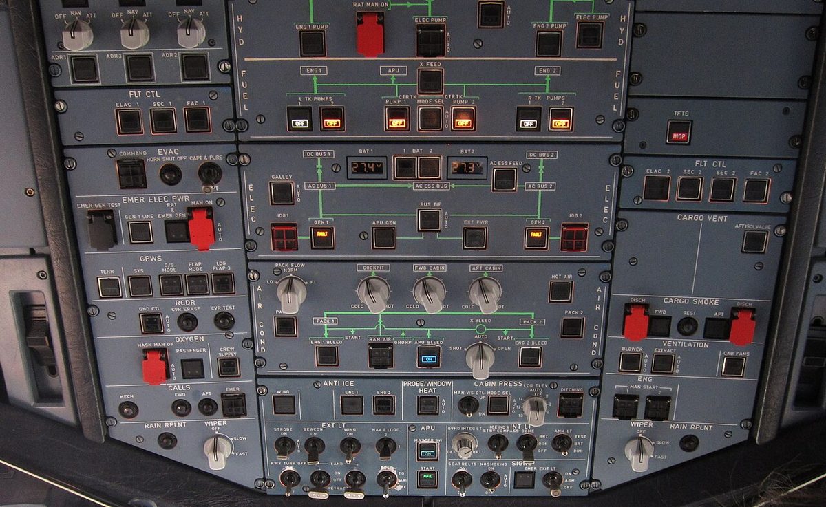
The MODE SEL pushbutton selects automatic or manual control of the two centre tank pumps.
- AUTO. The centre tank pumps run for 2 minutes at engine start, and outside that period whenever the slats are retracted. While the centre tank is feeding, the wing tanks tend to overfill, so when an inner tank is full the system stops the centre pump on that side until about 500 kg has been used from the inner tank, and then restarts it. The pumps stop automatically 5 minutes after the centre tank reaches low level.
- MAN. The crew control the pumps with the CTR TK PUMP pushbuttons. They run continuously and must be switched off when the centre tank is empty; the system does not stop them when an inner tank is full, so the wing tanks can overflow on the ground.
The amber MODE SEL FAULT light, with an ECAM caution, comes on when the centre tank holds more than 250 kg while a wing tank holds less than 5,000 kg, a sign that centre fuel is not being used as it should be. The CTR TK FEEDG memo shows that at least one centre tank pump is energised. If both centre pumps fail or are switched off, the centre quantity is boxed amber on the ECAM FUEL page and the remaining centre fuel is unusable.
An ACT has no pump. Its fuel is pushed into the centre tank by pressurising the ACT with air: the vent valve closes and the air shutoff valve opens. With the ACT pushbutton in AUTO the transfer runs in flight with the slats retracted, while an ACT low-level sensor is wet and once the centre tank high-level sensor has been dry for 10 minutes; it stops as soon as any condition is lost. FWD starts a manual transfer. The ACT FAULT light means the centre tank holds less than 3,000 kg while an ACT still holds more than 250 kg in AUTO.
Outer tank transfer
Two electrical outer-to-inner transfer valves in each wing let outer tank fuel drain into the inner tank. They open automatically when the inner tank reaches its low level, about 750 kg. Each inner tank has two low-level sensors, each of which controls one transfer valve in each wing, so both wings transfer together. Once open, the valves are latched open until the next refuelling, and the OUTR TK FUEL XFRD memo appears.
The 750 kg value assumes a level attitude without acceleration. In a steep descent, or when accelerating or decelerating, the valves can open with more fuel in the inner tanks, and the low-level warning can be triggered. If both transfer valves of one wing fail to open, the outer tank fuel is unusable: its quantity is boxed amber on the FUEL page and the fuel on board (FOB) indication is half-boxed amber.
Fuel recirculation and return
Fuel cools the integrated drive generators (IDGs). In the fuel recirculation system, some of the high-pressure fuel supplied to each engine passes through the IDG heat exchanger, where it absorbs heat, then through the fuel return valve (FRV) and back to the outer tank. If the outer tank is full, the returned fuel overflows into the inner tank through a spill pipe. The FADEC controls the FRV, so its logic belongs to the engine fitted. For the CFM56-5B, the FCOM gives two temperatures: the FRV mixes hot and cold fuel so that the returned fuel stays below 100 °C, and in flight it closes when the wing tank fuel temperature exceeds 52.5 °C. On the ground recirculation continues, even with an overflow in the surge tanks. Recirculation matters most with hot IDG oil at low engine power (see AC generators, CSD and IDG).
Quantity indication and level sensing
The fuel quantity indication (FQI) computer has two channels, the second taking over if the first fails. Capacitance probes in each tank measure the fuel level and temperature, giving a volume. A cadensicon (densitometer) in each inner tank measures the fuel density, and the FQI multiplies volume by density to obtain the mass. If a cadensicon fails, the capacitance index compensator (CIC) in each inner tank supplies the fuel's dielectric constant, from which the density is estimated. The FQI sends the total fuel mass, the quantity in each tank and the fuel temperatures to the ECAM, and controls automatic refuelling.
A separate fuel level sensing control unit (FLSCU) uses high, low and overflow level sensors and a fuel temperature sensor to switch the refuelling and defuelling valves, control the IDG cooling recirculation and control fuel transfers. The low-level warnings come from these sensors, so they are independent of the quantity displayed.
The upper ECAM display shows the FOB, including any ACT. Two dashes across its last two digits mean the FQI is in a degraded mode, and an amber half-box means that not all of the displayed fuel is usable. On the FUEL page, fuel used (FU) is reset when the engine is started on the ground. After the flight, the crew check that fuel on board plus fuel used agrees with the departure fuel; an unusual difference calls for maintenance action. Advisories appear for a wing imbalance above 1,500 kg and for high or low fuel temperatures (see fuel quantity and temperature indication).
Refuelling and defuelling
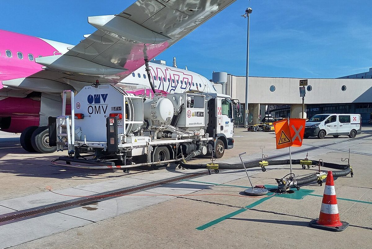
Pressure refuelling uses one or two coupling points under the wings, on the right side and, if installed, the left. On the refuel control panel the operator sets the preselected fuel quantity; the ACTUAL display shows the fuel on board.
In automatic refuelling the outer tanks are filled first; if the preselected load is more than the wing tanks can hold, the centre tank is filled at the same time. A full outer tank overflows into the inner tank through a spill pipe. Each refuel valve closes automatically when the tanks contain the preselected load or when the system detects a high fuel level, which lights the blue HI LVL light for that tank. A steady green END light means refuelling is complete; a flashing END light means it was stopped, for example by an electrical transient when the power source changes, and the preselected quantity must be entered again. At nominal pressure the wing tanks take about 17 minutes and all tanks, without ACT, about 20 minutes.
In manual refuelling the wing tanks are filled first, then the centre tank, then the ACTs. Battery power refuelling is possible: the BATT POWER switch makes HOT BUS 1 supply the FQI, which tests itself for about 40 seconds, and the supply cuts off after 10 minutes without a refuel selection or at the end of refuelling. The wing tanks can also be filled by gravity through filling points on top of the wings. For defuelling, DEFUEL XFR opens the transfer valve between the engine feed system and the refuel gallery, and the tank pumps push fuel back out through the coupling. The same valve allows fuel to be transferred between tanks.
Low level alerts and minimum fuel
The fuel low level warning, FUEL L(R) WING TK LO LVL, is triggered when a wing tank contains less than 750 kg. It comes from the FLSCU level sensor and is independent of the FQI, so it is a cross-check on the gauges. The minimum fuel for take-off is 1,500 kg, and no wing tank low-level alert may be displayed for take-off.
Imbalance limits apply as well. At take-off the inner tanks may differ by 500 kg when the heavier one is full, more as the quantities fall, and the outer tanks by 370 kg. In flight and at landing the inner tanks may differ by 1,500 kg when full, with no limit below 2,250 kg per side, and the outer tanks by 690 kg under conditions. These limits may be exceeded after a fuel system failure without significant effect on handling.
Exam tip: about 750 kg is both the inner tank level at which the outer-to-inner transfer valves open and the wing tank level that triggers the LO LVL warning. Both come from level sensors, not from the fuel quantity indication.
A low-level alert is a fuel state, not a flight plan. The crew's plan rests on the final reserve and the ICAO MINIMUM FUEL and MAYDAY FUEL declarations described in fuel planning and fuel reserves and in-flight fuel management.
Frequently asked questions
In what order does the A320 use its fuel?
With the mode selector in AUTO, fuel from any additional centre tanks is first transferred into the centre tank. The centre tank then feeds the engines, because its pumps deliver at a higher pressure than the wing pumps. The inner wing tanks follow, and when an inner tank is down to about 750 kg the outer tank fuel drains into it. Outer fuel is kept until last for wing bending and flutter relief.
How much fuel does the A320 hold?
Without additional centre tanks the usable capacity is 24,209 litres, about 19,004 kg at a density of 0.785 kg per litre. Each inner wing tank holds 7,099 litres, each outer tank 880 litres and the centre tank 8,250 litres. Each additional centre tank adds 2,992 litres, so with two of them the total is 30,193 litres, about 23,702 kg.
What is the minimum fuel for take-off on the A320?
The FCOM limitation is 1,500 kg, and in addition no ECAM alert related to a low fuel level in the wing tanks, such as FUEL WING TK LO LVL, may be displayed for take-off. The low-level alert is triggered when a wing tank contains less than about 750 kg, by a level sensor that is independent of the fuel quantity indication.
What does the MODE SEL pushbutton do on the A320 fuel panel?
It selects automatic or manual control of the centre tank pumps. In AUTO they run for 2 minutes at engine start, then whenever the slats are retracted, stop when an inner tank is full and stop 5 minutes after the centre tank reaches low level. In MAN they run continuously and must be switched off when the centre tank is empty. Its FAULT light means the centre tank holds over 250 kg while a wing tank holds under 5,000 kg.
Why does the A320 return fuel to the wing tanks?
To cool the integrated drive generators. Some high-pressure fuel from each engine passes through the IDG heat exchanger and returns, through a fuel return valve controlled by the FADEC, to the outer tank, overflowing to the inner tank if the outer tank is full. On the CFM56-5B the returned fuel is kept below 100 degrees C, and in flight the return stops if the wing tank fuel exceeds 52.5 degrees C.
Test yourself on A320 Fuel System
The v1prep banks cover this topic in the A320 type-rating bank, with a worked explanation for every answer. EASA ATPL, PPL, IR and CPL, the FAA written tests and A320/B737 type ratings.
Start practising →Sources and further reading
- EASA Easy Access Rules for Large Aeroplanes (CS-25), CS 25.951 to CS 25.1001, fuel system
- EASA TCDS EASA.A.064 (Airbus A318/A319/A320/A321), Explanatory Note, Annex I, Special Condition F-13 Fuel System Low Level Indication - Fuel Exhaustion
- EASA Type Certificate Data Sheet EASA.A.064, Airbus A318, A319, A320, A321
- FAA Aviation Maintenance Technician Handbook, Airframe (FAA-H-8083-31B), Chapter 14, Aircraft Fuel System
- EASA, Explanatory Note to ED Decision 2018/001/R, Part-FCL theoretical knowledge learning objectives (021 Airframe and Systems)
Library articles are written for study and exam preparation. They do not replace your aircraft's approved documentation, your operator's procedures or the regulations themselves.