B737 Flight Controls: Roll, Yaw and Speedbrakes
On the Boeing 737, roll is controlled by two ailerons and eight flight spoilers and yaw by a single rudder, moved on the 737 NG through cables and hydraulic power control units, with two yaw dampers acting on the rudder; the flight spoilers also serve as speedbrakes, joined on the ground by four ground spoilers.
The Boeing 737 controls roll with two ailerons and eight flight spoilers, and yaw with a single rudder. As in pitch, the pilots' controls are connected by cables to hydraulic power control units (PCUs) powered by systems A and B, and either system can operate all the primary flight controls on its own. The roll controls are duplicated in an unusual way: the captain's control wheel drives the ailerons and the first officer's wheel the spoilers, with a mechanism between them that lets either path carry on if the other jams.
The rudder has a main PCU with an actuator for each of systems A and B and a separate standby PCU powered by the standby hydraulic system, protected by a load limiter and a force fight monitor and fed by two yaw dampers. The same spoiler panels used for roll serve as speedbrakes in flight and, with the ground spoilers, as lift dumpers on landing. This article describes the 737 NG and notes where the 737 MAX differs; pitch control is covered in B737 pitch and stabiliser trim.
Roll control: ailerons and flight spoilers
The captain's control wheel is connected by cables to the aileron PCUs through the aileron feel and centering unit. The first officer's control wheel is connected by cables to the spoiler PCUs through the spoiler mixer. In normal operation the two wheels move together.
The flight spoilers start to deflect once the wheel is turned more than about 10°. They rise on the wing whose aileron goes up and stay faired on the wing whose aileron goes down. Each hydraulic system is dedicated to different spoiler pairs, system A to flight spoilers 2, 4, 9 and 11 and system B to 3, 5, 8 and 10, so that the spoilers stay symmetric if one system fails. The guarded flight spoiler switches, normally ON, close the respective flight spoiler shutoff valve at OFF; they are used for maintenance only.
Aileron trim is commanded by two spring-loaded switches that must be moved together; they reposition the aileron neutral position, and the control wheel shows the trim. With the autopilot engaged, aileron trim is prohibited, a memory limitation: the autopilot overpowers the trim and holds the wheel where it needs it, so the trim does not show on the wheel and the aeroplane can roll abruptly when the autopilot is disengaged.

Manual reversion and jam override
The control columns and wheels are connected through transfer mechanisms that let the pilots bypass a jammed control or surface. In roll, the two control wheels are joined by the control wheel transfer mechanism, which the FCOM describes as the aileron transfer mechanism:
- Aileron system jammed. Force on the first officer's wheel gives roll control from the spoilers. The ailerons and the captain's wheel are inoperative.
- Spoiler system jammed. Force on the captain's wheel gives roll control from the ailerons. The spoilers and the first officer's wheel are inoperative.
If both systems A and B are lost, the aeroplane is flown in manual reversion: the ailerons and elevators are operated manually, while the rudder is powered by the standby system. The spoilers, powered only by A and B, are lost. With both FLT CONTROL switches at STBY RUD, the standby yaw damper can be engaged, and it then turns control wheel movement into rudder, a rudder assist that helps turn the aeroplane while the ailerons are in manual reversion.
Rudder and standby rudder PCU
The rudder pedals move the rudder and also give limited nose wheel steering, up to 7° either side. During the take-off roll the rudder becomes aerodynamically effective between 40 and 60 kt. Rudder trim is set with a spring-loaded knob that trims the rudder electrically; an amber OFF flag on the rudder trim indicator means the indicator itself is inoperative.
The main rudder PCU has two independent input rods, two control valves and two actuators, one for system A and one for system B. The standby rudder power control unit has its own input rod and control valve and is powered by the standby hydraulic system. All three input rods have individual jam override mechanisms: if one rod or the hardware downstream of it jams, the input still reaches the other two.
The standby rudder is pressurised in three ways: with either FLT CONTROL switch at STBY RUD, automatically during take-off or landing when system A or B is lost, or automatically by the force fight monitor. The standby rudder system is described from the hydraulic side in B737 hydraulic system.
Rudder protections
The rudder load limiter limits rudder authority at high speed. Above 137 kt it reduces the maximum hydraulic pressure of both systems A and B inside the main rudder PCU by about 25 percent each, and it restores full authority when the speed falls below 132 kt.
The force fight monitor (FFM) in the main rudder PCU detects opposing pressure between the A and B actuators, a force fight, which can happen if the A or B input is jammed or disconnected. Its output automatically turns on the standby hydraulic pump, opens the standby rudder shutoff valve to pressurise the standby rudder PCU, and lights STBY RUD ON, MASTER CAUTION and FLT CONT. General principles are covered in yaw dampers and rudder limiting.
Yaw dampers and SMYD
The 737 has a main yaw damper and a standby yaw damper, both controlled by two SMYD (stall management yaw damper) computers. The SMYDs receive both ADIRUs, both control wheels and the YAW DAMPER switch, and send yaw damper commands to the main rudder PCU or the standby rudder PCU as appropriate. Either yaw damper gives Dutch roll prevention, gust damping and turn coordination, and yaw damper action does not move the rudder pedals.
The main yaw damper uses system B, with the SMYDs monitoring it continuously. The YAW DAMPER switch at ON engages:
- the main yaw damper to the main rudder PCU, if the B FLT CONTROL switch is ON;
- the standby yaw damper to the standby rudder PCU, if both FLT CONTROL switches are at STBY RUD.
The amber YAW DAMPER light shows the yaw damper is not engaged. The switch moves to OFF by itself, the light comes on and the switch cannot be reset if the SMYD senses a yaw damper fault, if the yaw damper does not respond to a command, or if the B FLT CONTROL switch is at OFF or STBY RUD. On some variants a YAW DAMPER indicator shows the main yaw damper's movement of the rudder, but not the pilots' pedal inputs.
The SMYDs also give stall warning: they decide when it is needed from the angle of attack vanes, the ADIRUs, anti-ice, configuration, air/ground sensing and thrust, and each STALL WARNING TEST switch tests one of them on the ground. If the AUTO SLAT FAIL light comes on only during a MASTER CAUTION recall, it reports the failure of a single SMYD.
Speedbrakes and ground spoilers
The speedbrakes consist of the flight spoilers and the ground spoilers: four panels, two on the upper surface of each wing, all powered by system A. The SPEED BRAKE lever has four positions:
| Position | Effect |
|---|---|
| DOWN (detent) | All flight and ground spoilers faired |
| ARMED | Automatic speed brake system armed; at touchdown the lever moves to UP and all spoilers extend |
| FLIGHT DETENT | All flight spoilers at their maximum in-flight position |
| UP | All flight and ground spoilers fully extended, for ground use |
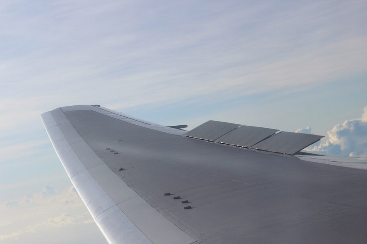
Moving the lever beyond the FLIGHT DETENT in flight causes buffeting and is prohibited. Boeing's operational information also says not to deploy the speedbrakes in flight below 1,000 ft radio altitude.
On landing with the lever ARMED, the system deploys all spoilers when the SPEED BRAKE ARMED light is on, the radio altitude is below 10 ft, a gear strut compresses, both thrust levers are at IDLE and the main wheels spin up above 60 kt. Compression of any gear strut enables the flight spoilers; compression of the right main gear strut opens the ground spoiler interlock valve through a mechanical linkage, which lets the ground spoilers deploy. With the lever left DOWN, on a landing or a rejected take-off the system still works once the wheels spin up above 60 kt, both thrust levers are at IDLE and the reverse thrust levers are raised. If either thrust lever is then advanced, the lever returns to DOWN and all panels retract.
The lights next to the lever:
- SPEED BRAKE ARMED (green): valid automatic speed brake inputs; deactivated with the lever DOWN.
- SPEED BRAKE DO NOT ARM (amber): abnormal or test inputs to the automatic system; or, during landing, wheel speed below 60 kt with the lever not DOWN.
- SPEEDBRAKES EXTENDED (amber): in flight, lever beyond ARMED with the trailing edge flaps beyond 10 or below 800 ft radio altitude; on the ground, lever DOWN with the ground spoilers not stowed (not shown when system A pressure is below 750 psi).
After touchdown the pilot flying checks the lever is UP and the pilot monitoring calls "SPEED BRAKES UP" or "SPEED BRAKES NOT UP". The take-off configuration warning sounds if the lever is not DOWN, or if the spoiler control valve is sending pressure to the ground spoiler interlock valve.
Surface position indication
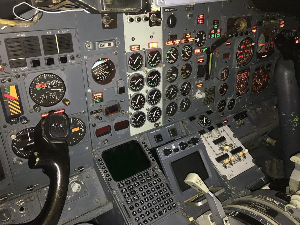
The flight control surface position indicator can be shown on the lower display unit, where the crew watch the surfaces move during the flight control check before taxi. Its RUDDER scale includes the main and standby yaw damper movement of the rudder. Its FLT SPLR scales show flight spoilers 4 and 9 only. The ELEV scale's centre mark is the elevator's neutral position on the ground with the stabiliser trimmed in the green band; elevator neutral varies with stabiliser position, flaps and Mach.
Uncommanded rudder or roll
The Uncommanded Rudder / Yaw or Roll recall items cover a rudder or roll input the crew did not make:
- Autopilot (if engaged): disengage, so every control surface is available by hand.
- Maintain control with all available flight controls.
- If roll is uncontrollable, immediately reduce pitch attitude and angle of attack and increase airspeed; do not try to hold altitude until control is recovered.
- Once roll is controllable, disengage the autothrottle (if engaged) and check that thrust is symmetrical, since asymmetric thrust may be the cause.
Two 737 MAX differences concern this side of the flight controls. Its spoilers are fly-by-wire instead of cable-driven, adding manoeuvre load alleviation, the landing attitude modifier, the elevator jam landing assist and emergency descent speedbrakes, with new SPOILERS and ASSIST ON lights. And the roll command alerting system, with its ROLL/YAW ASYMMETRY and ROLL AUTHORITY alerts, is standard on the MAX and optional on the NG.
Frequently asked questions
How is roll controlled on the Boeing 737?
By two ailerons and eight flight spoilers. On the 737 NG the captain's control wheel is connected by cables to the aileron power control units through the aileron feel and centering unit, and the first officer's wheel to the spoiler units through the spoiler mixer. The spoilers start to rise once the wheel is turned more than about 10 degrees, and only on the wing whose aileron goes up.
What happens if the ailerons jam on the 737?
The control wheels are linked by a transfer mechanism that lets the pilots bypass a jammed control or surface. If the aileron system jams, force on the first officer's control wheel gives roll control from the spoilers, while the ailerons and the captain's wheel are inoperative. If the spoiler system jams, force on the captain's wheel gives roll through the ailerons instead.
What is the rudder load limiter on the 737?
Above 137 kt, the load limiter reduces the maximum hydraulic pressure of systems A and B inside the main rudder power control unit by about 25 percent each, limiting rudder authority at high speed. Full authority returns when the airspeed falls below 132 kt. The function works automatically, with no crew action.
What does the 737 SMYD do?
The two stall management yaw damper computers receive both ADIRUs, both control wheels and the yaw damper switch, and send yaw damper commands to the main or standby rudder power control unit. Either yaw damper gives Dutch roll prevention, gust damping and turn coordination without moving the pedals. The same two computers also decide when stall warning is needed.
When does the SPEED BRAKE DO NOT ARM light come on?
The amber light shows an abnormal condition or test inputs to the automatic speed brake system. During landing it also comes on when the wheel speed has dropped below 60 kt and the speed brake lever is not in the DOWN detent, a cue to stow the lever. Before flight the crew check that it is out, together with the SPEED BRAKE ARMED and SPEEDBRAKES EXTENDED lights.
Test yourself on B737 Flight Controls: Roll, Yaw and Speedbrakes
The v1prep banks cover this topic in the B737 type-rating bank, with a worked explanation for every answer. EASA ATPL, PPL, IR and CPL, the FAA written tests and A320/B737 type ratings.
Start practising →Sources and further reading
- FAA Flight Standardization Board Report, Boeing 737, Revision 17
- EASA Type Certificate Data Sheet IM.A.120, Boeing 737
- EASA Easy Access Rules for Large Aeroplanes (CS-25), CS 25.671 and CS 25.672, control systems and stability augmentation
- 14 CFR 25.671, Control systems, general
- 14 CFR 25.672, Stability augmentation and automatic and power-operated systems
- FAA Aviation Maintenance Technician Handbook, Airframe (FAA-H-8083-31B), Aircraft Structures, flight control surfaces
Library articles are written for study and exam preparation. They do not replace your aircraft's approved documentation, your operator's procedures or the regulations themselves.