B737 Electrical System
The Boeing 737 electrical system supplies three-phase 115 V, 400 Hz AC from two engine-driven integrated drive generators, the APU generator or ground power, never paralleling two sources, and 28 V DC through three transformer rectifiers, with two batteries and a static inverter keeping the essential standby buses powered.
The Boeing 737 electrical system is built on two rules: AC sources are never paralleled, and a source connected to a transfer bus automatically disconnects the source already there. It has three parts: the AC power system, the DC power system and the standby power system, which keeps essential equipment alive on battery power when every generator has gone.
This article follows the 737 NG flight crew operations manual (FCOM); the 737 MAX shares the type rating, and the differences that touch this system are noted. The general principles are in electrical power distribution, AC generators, CSD and IDG and aircraft batteries.

- System overview and power sources
- Generators and generator drives
- AC transfer buses and bus transfer
- DC system and TR units
- Batteries and hot battery buses
- Standby power system
- Ground power and ground service
- Galley and cabin loads
- Electrical panel lights and metering
- Power-up and abnormal operation
- Frequently asked questions
System overview and power sources
| Source | Supplies | Notes |
|---|---|---|
| IDG 1 and IDG 2 | Three-phase 115 V, 400 Hz AC | Primary power, one per engine, each to its own transfer bus |
| APU generator | Both AC transfer buses | Ground or flight; alone it meets all ground and most flight needs |
| External power | Both AC transfer buses | Receptacle near the nose gear wheel well, lower right side |
| TR1, TR2, TR3 | 28 V DC | Fed from the AC transfer buses |
| Main and auxiliary batteries | 24 V DC | Standby power, hot battery buses, APU start |
The APU generator can carry an electrical load up to 41,000 ft. The 737 MAX keeps the NG's Honeywell 131-9[B] APU but removes its APU MAINT light and adds a retractable door with a DOOR light.
Generators and generator drives
Each engine drives an integrated drive generator (IDG), which keeps the generator at constant speed, and so constant frequency, across the engine's normal operating range. A voltage regulator controls the output voltage; an integral electromechanical disconnect device can isolate the IDG mechanically.
The generator switch (GEN) at ON connects the IDG to its AC transfer bus by disconnecting the previous source and closing the generator circuit breaker; at OFF it opens the breaker. The blue GEN OFF BUS light means the IDG is not supplying its transfer bus. Both GENERATOR switches are set ON in the before taxi procedure.
The amber generator drive (DRIVE) light shows low IDG oil pressure, caused by an IDG failure, an engine shutdown, an automatic disconnect for high oil temperature or a disconnect through the switch. The guarded generator drive DISCONNECT switch disconnects the IDG only if electrical power is available and the engine start lever is at IDLE. The IDG cannot be reconnected in the air.
The auto generator on-line feature covers a take-off on APU power: if the APU, powering both transfer buses at take-off, then shuts down or fails, the engine generators connect automatically to their transfer buses. This happens only once per flight, and only in that situation.
AC transfer buses and bus transfer
Each side's AC system has an AC transfer bus, a main bus, two galley buses and a ground service bus. The transfer buses feed the TRs and the standby system's normal supply. The amber TRANSFER BUS OFF light means its transfer bus is not powered. The amber SOURCE OFF light means that no source has been manually selected for that transfer bus, or that the selected source has been disconnected.
The FCOM calls the link between the two sides the bus tie system. In general terms, a tie bus is a switchable connection between two main buses that lets one generator supply both when the other fails; on the 737 the bus transfer breakers (BTBs) make that connection between the two AC transfer buses. With the guarded BUS TRANSFER switch at AUTO, if the source on one transfer bus fails or is disconnected, the source on the other side picks it up through the BTBs. At OFF, the BTBs isolate the two transfer buses when one IDG is powering both, the DC cross tie relay opens, and TR3 cannot take its input from transfer bus 1.
Note: SOURCE OFF is not TRANSFER BUS OFF: with a source selected for the other side, the BTBs power both buses and SOURCE OFF stays lit on a live bus.
Of ground power and the APU, whichever is selected last powers both transfer buses: one bus cannot be on external power and the other on the APU. When an engine generator is then connected to its own side, external power or the APU keeps the other. With both transfer buses on IDGs, one APU GEN switch ON takes only its own side; with neither on an IDG, a single APU GEN switch ON connects both buses to the APU, drops external power and leaves the opposite SOURCE OFF light lit until the second switch is moved. The blue APU GEN OFF BUS light means the APU is running and not powering a bus.
DC system and TR units
Three transformer rectifier units (TRs) convert 115 V AC to 28 V DC. TR1 is fed from AC transfer bus 1 and TR2 from AC transfer bus 2. With BUS TRANSFER at AUTO, TR3 is normally fed from transfer bus 2, with transfer bus 1 as its backup. Any two TRs can carry the total connected DC load.
Normally the cross bus tie relay is closed and connects DC bus 1, DC bus 2 and the DC standby bus, so TR1 and TR2 each power all three. TR3 powers the battery bus and backs up TR1 and TR2. The relay opens automatically at glideslope capture on a flight director or autopilot ILS approach, so that a single failure cannot affect both navigation receivers and both flight control computers, and whenever BUS TRANSFER is set OFF.
The amber TR UNIT light has two meanings. On the ground it comes on if any TR has failed; in flight, only if TR1 has failed, or TR2 and TR3 have both failed. The amber ELEC light shows a fault in the DC power system or the standby power system and works only on the ground.
Batteries and hot battery buses
The 737 carries two 24 V nickel-cadmium batteries, the main and the auxiliary battery, in the electronics compartment, with a voltage range of 22 to 30 V. The auxiliary battery works in parallel with the main battery only when the battery is powering the standby system; at all other times it is isolated. Two fully charged batteries provide standby power for at least 60 minutes.
The hot battery bus is always connected to the battery, with no switch, though the battery must be above minimum voltage to run its loads. The switched hot battery bus is powered whenever the battery switch is ON.
The guarded battery switch (BAT) at ON powers the switched hot battery bus and energises the relays that switch the standby system to battery power if normal power is lost. At OFF it removes power from the battery bus and the switched hot battery bus; with the battery as the only source, also from the DC standby bus, the static inverter and the AC standby bus. The APU needs the battery switch ON, and selecting it OFF shuts the APU down. The amber BAT DISCHARGE light means that, with the battery switch ON, an excessive battery discharge has been detected.
The main battery charger is fed from AC ground service bus 2, the auxiliary charger from ground service bus 1. After its primary charge cycle the main charger becomes a constant-voltage TR for the hot and switched hot battery buses, and it powers the battery bus if TR3 fails.
Standby power system
The standby power system supplies 115 V AC and 28 V DC to essential systems if all engine and APU generator power is lost. It consists of the static inverter, the AC standby bus, the DC standby bus, the battery bus, the hot battery bus, the switched hot battery bus and the two batteries.
| Bus | Normal supply | Supply on batteries |
|---|---|---|
| AC standby bus | AC transfer bus 1 | Batteries through the static inverter |
| DC standby bus | TR1, TR2 and TR3 | Batteries directly |
| Battery bus | TR3 | Batteries directly |
| Hot and switched hot battery buses | Battery and charger | Batteries directly |
The static inverter converts 24 V DC from the battery into 115 V AC for the AC standby bus; the standby power and battery switches control its supply. With the standby power switch at AUTO, the standby buses go to the batteries automatically if power from AC transfer bus 1 or DC bus 1 is lost. BAT, the unguarded position, overrides the automatic switching and puts the AC standby, DC standby and battery buses on the battery, though with the battery switch OFF the switched hot battery bus is lost. OFF, the centre position, removes power from the AC standby bus, the static inverter and the DC standby bus. The amber STANDBY PWR OFF light means that the AC standby bus, the DC standby bus or the battery bus is unpowered.
Flying on batteries
With all generators lost, the batteries keep, among other things:
- the captain's primary flight and navigation displays, the clocks and the left EFIS control panel;
- the left FMC and CDU, VHF NAV 1, ILS 1, the left IRS and GPS, and VHF 1 with the interphones and passenger address;
- the engine indications on the upper display unit, the fuel shutoff and crossfeed valves and fuel quantity;
- the captain's pitot heat, the only anti-ice left, the fire protection, the stall warning and the aural warnings;
- inboard antiskid, the parking brake, the gear indicator lights, the standby compass, dome and instrument flood lights, and crew and passenger oxygen.
APU start attempts are not recommended above 25,000 ft. This list is the NG's; the 737 MAX, with four large displays and an integrated standby flight display, has its own.
Ground power and ground service
The blue GRD POWER AVAILABLE light shows that ground power is connected and meets the aircraft's power quality standards. The ground power switch (GRD PWR) is a three-position switch, spring-loaded to neutral. Moved momentarily to ON with ground power available, it removes the previous source from the AC transfer buses and connects ground power if its quality is correct. With both generator switches OFF or both engines shut down on the ground, it connects external power to both transfer buses.
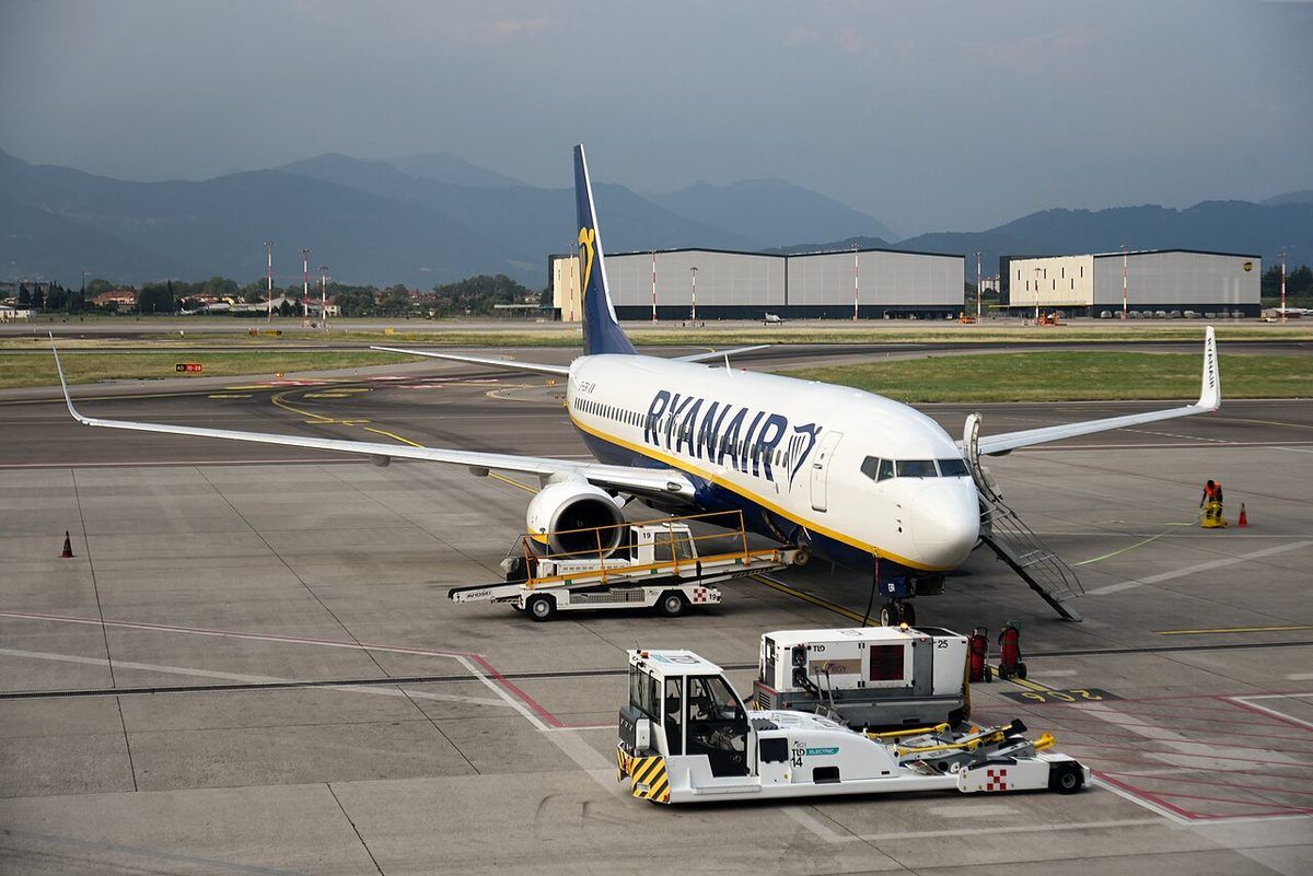
The ground service switch, a momentary pushbutton on the forward attendant panel, controls the ground service buses, so the aeroplane can be serviced on external power without powering the AC transfer buses. It lights white when external power is on the ground service buses and is overridden when both transfer buses are powered.
Galley and cabin loads
The CAB/UTIL switch at OFF removes power from all 115 V AC galley buses and from cabin equipment such as the recirculation fans, the door area and drain mast heaters, the lavatory water heaters, the logo lights and the potable water compressor. The IFE/PASS SEAT switch at OFF removes power from the in-flight entertainment, the passenger seat outlets and the cabin telephone.
Automatic load shedding works on sensed load. With a single generator, the galleys and main bus on AC transfer bus 2 go first, then those on transfer bus 1, then the IFE buses, as long as the overload persists. In flight on the APU alone, all galley and main buses are shed, and the IFE buses if needed; on the ground the APU tries to carry the full load and sheds only on overload. Switching CAB/UTIL OFF and back ON attempts to restore the shed buses.
Electrical panel lights and metering
The AC/DC metering panel lets the crew read AC voltage and frequency for standby power, ground power, generator 1, the APU generator, generator 2 and the static inverter; frequency appears only when the generator is excited. DC voltage and current can be read for the battery and each TR, and voltage only for standby power and the battery bus. During an APU start on battery power alone, the APU GEN selection shows no frequency and zero volts until the APU GEN OFF BUS light comes on. On the panel, blue lights such as GEN OFF BUS are information; amber lights need the crew's timely attention.
Power-up and abnormal operation
The FCOM's Electrical Power Up supplementary procedure precedes the preliminary preflight procedure, which assumes it is complete. The battery switch matters first: it powers the switched hot battery bus, arms the standby transfer and is needed for the APU. The APU starter uses AC from transfer bus 1 if available, otherwise the main battery, and APU GEN OFF BUS shows that the APU can take a load; ground power goes on with GRD PWR once GRD POWER AVAILABLE is lit. The stall warning test needs the transfer buses powered for up to 4 minutes.
At shutdown, if APU power is needed, the crew check APU GEN OFF BUS lit, select both APU generator switches ON and check that the SOURCE OFF lights go out. In flight, after an IDG is lost, the BTBs give its transfer bus to the other source and the APU generator can be connected as a second source; after a dual generator loss the standby system runs on the batteries.
Frequently asked questions
What is the difference between SOURCE OFF and TRANSFER BUS OFF on the 737?
TRANSFER BUS OFF means the transfer bus itself is not powered. SOURCE OFF means only that no source has been manually selected for that transfer bus, or that the selected source has been disconnected. If a source has been selected for the opposite side, the bus transfer breakers can power both transfer buses with SOURCE OFF still lit, so SOURCE OFF alone does not mean a dead bus.
What does the 737 standby power system power and for how long?
It supplies 115 V AC and 28 V DC to essential systems when all engine and APU generator power is lost. The batteries then feed the DC standby bus, the battery bus and the hot battery buses directly, and the AC standby bus through the static inverter. Two fully charged batteries provide standby power for at least 60 minutes, with the auxiliary battery working in parallel with the main battery.
Why does the 737 cross bus tie relay open on an ILS approach?
At glideslope capture during a flight director or autopilot ILS approach, the cross bus tie relay opens and isolates DC bus 1 from DC bus 2. This prevents a single failure from affecting both navigation receivers and both flight control computers during the approach. The relay also opens when the BUS TRANSFER switch is set to OFF.
Can a 737 IDG be reconnected in flight?
No. The guarded generator drive DISCONNECT switch disconnects the IDG only if electrical power is available and the engine start lever is at IDLE, and the IDG cannot be reconnected in the air. The amber DRIVE light shows low IDG oil pressure, which can come from an IDG failure, an engine shutdown, an automatic disconnect for high oil temperature or a disconnect by the switch.
What is the auto generator on-line feature on the 737?
If the aeroplane takes off with the APU powering both transfer buses and the APU then shuts down or fails, the engine generators are connected automatically to their own transfer buses. The feature works only once per flight and only in that situation, so the crew are not left on batteries because the generators were not selected before take-off.
Test yourself on B737 Electrical System
The v1prep banks cover this topic in the B737 type-rating bank, with a worked explanation for every answer. EASA ATPL, PPL, IR and CPL, the FAA written tests and A320/B737 type ratings.
Start practising →Sources and further reading
- EASA Type Certificate Data Sheet IM.A.120, Boeing 737
- FAA Flight Standardization Board Report, Boeing 737
- EASA Easy Access Rules for Large Aeroplanes (CS-25), CS 25.1351 to 25.1365, electrical systems and equipment
- 14 CFR 25.1351, Electrical Systems and Equipment, General
- FAA Aviation Maintenance Technician Handbook, Airframe (FAA-H-8083-31B), Aircraft Electrical System
- EASA Easy Access Rules for Aircrew (Regulation (EU) No 1178/2011), ATPL and CPL theoretical knowledge learning objectives, subject 021
Library articles are written for study and exam preparation. They do not replace your aircraft's approved documentation, your operator's procedures or the regulations themselves.