A320 Auto Flight: FCU and AP/FD Modes
The A320 auto flight system comprises two autopilots and two flight directors, computed by the flight guidance part of the FMGCs and commanded from the flight control unit on the glareshield, whose lateral, vertical and common modes follow either managed targets from the FMS or targets selected by the crew.
The A320 has two autopilots (AP) and two flight directors (FD), computed by the flight guidance part of its two FMGCs (see A320 FMGS and MCDU). The crew command them from the Flight Control Unit (FCU) on the glareshield and read what they are doing on the Flight Mode Annunciator (FMA) at the top of each PFD. The autopilot generates pitch, roll and yaw orders and also steers the nosewheel.
The modes are lateral, vertical or common, and each can be managed or selected. Airbus's third golden rule sums up their use: understand the FMA at all times. Approach and landing modes are covered in A320 auto flight: approach, landing and go-around, the autothrust in A320 autothrust and thrust levers.
FCU and managed vs selected guidance
The FCU consists of three control panels: one for the auto flight system in the centre and one EFIS control panel at each end. It has two channels, each able to command all of its functions alone.
Each FCU knob works the same way. Pushing a knob arms or engages managed guidance for that function; pulling it engages selected guidance with the value shown in the window as target. A managed target shows dashes in the window with a white dot lit; a selected target shows its value, with the dot off. Selected guidance always has priority over managed guidance. The altitude window is the exception: it always shows a value selected by the crew and never dashes.
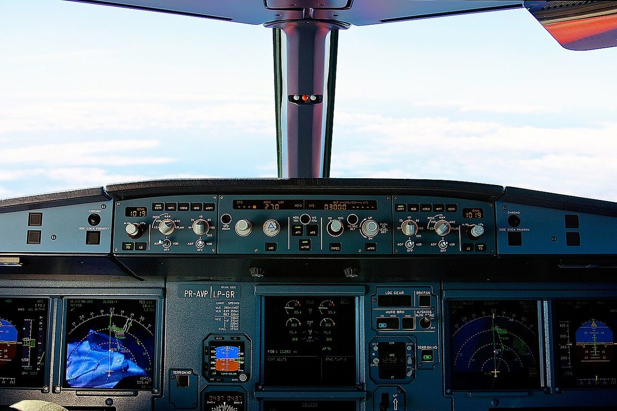
| Knob | Range and steps |
|---|---|
| SPD/MACH | 100 to 399 kt, M 0.10 to 0.99; one turn about 32 kt or M 0.32 |
| HDG/TRK | 0 to 359°, 1° per click; one turn 32° |
| ALT | 100 to 49,000 ft, in 100 ft or 1,000 ft steps set by the outer ring |
| V/S | ±6,000 ft/min; two clicks give 100 ft/min when turned slowly |
| FPA | ±9.9°, 0.1° per click; one turn 3.2° |
Turning a knob without pulling it preselects a value: the speed window shows it for 10 s, the heading and V/S windows for 45 s, and a preselected V/S or FPA not engaged within 45 s is cancelled. Pushing the V/S/FPA knob levels the aircraft at once with a zero V/S or FPA target. The HDG-V/S / TRK-FPA pushbutton switches the FCU reference between heading with vertical speed and track with flight path angle; with TRK-FPA the PFDs show the green flight path vector. The default at power-up is HDG-V/S.
After take-off the speed knob can be pulled 5 s after lift-off at the earliest. With the AP on, the PF makes the FCU entries, or the PM at the PF's request; with the AP off, the PM makes them at the PF's request, although the PF may engage the AP and A/THR.
Flight Mode Annunciator
The FMA reads from left to right: autothrust mode, vertical mode, lateral mode, then the approach capability and the engagement status of the APs, FDs and A/THR. A typical expedite climb thus reads THR CLB, EXP CLB, NAV. The FD status shows which flight director drives which PFD: if FD 2 is switched off, the FMA shows 1FD-; if FD 2 fails instead, both PFDs take FD 1's orders and the FMA shows 1FD1.
The FMA must be monitored, announced, confirmed and understood. When a mode reverts without crew action, the FMA draws attention to it: the new mode is boxed for 10 s, the triple click sounds and the FD bars flash.

AP/FD engagement and disconnection
Both FDs engage automatically at power-up on the ground. In flight they engage automatically when SRS GA engages or when the AP/FD TCAS mode engages on a resolution advisory. An FD switched on with no AP or FD previously engaged comes up in HDG (or TRK) and V/S (or FPA), its bars flashing for 10 s; an AP engaged with no FD engaged also comes up in these basic modes. The FD bars disappear when the bank exceeds 45° or the pitch exceeds 25° up or 13° down.
An AP engages when AP1 or AP2 is pressed, provided the aircraft has been airborne for more than 5 s and pitch, bank and speed are in range; the limitations set a minimum of 100 ft AGL and 5 s after lift-off, and 500 ft AGL for phases without a specific figure. The APs are available only in normal and alternate law.
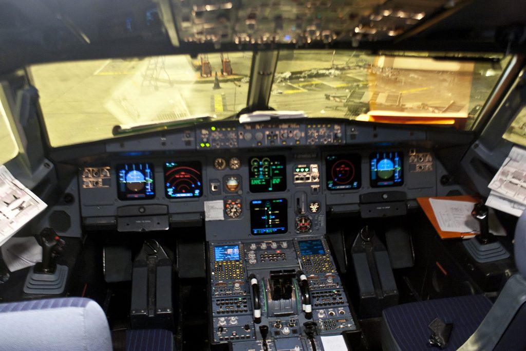
When an AP engages, both sidesticks lock in neutral and the rudder pedals need more force; pilot and AP cannot give simultaneous inputs. The second AP can engage only with LOC and G/S armed, captured or tracked, or with go-around engaged. With both engaged, AP1 is active whatever the order of engagement.
In normal law the APs disengage automatically when the bank exceeds 45°, the pitch exceeds 25° up or 13° down, or the high-speed or angle-of-attack protection activates. Pressing the AP pushbutton on the FCU, or acting beyond a threshold on the sidestick, the rudder pedals (more than 10° out of trim) or the pitch trim wheel, disengages them too; on the ground so does setting all thrust levers above the MCT detent.
The standard disconnection is two presses of the sidestick takeover pushbutton. The first press disengages the AP and triggers the AP OFF message on the PFDs and the warning display, a low-volume cavalry charge and the MASTER WARN light; the second cancels them. If the second press is slow, the cavalry charge becomes loud and AUTO FLT AP OFF appears. The autothrust has its own instinctive disconnect pushbuttons, on the thrust levers.
Take-off modes: SRS and RWY
The Speed Reference System (SRS) is the take-off pitch mode. It needs V2 on the PERF TAKE OFF page: without it, V/S engages 5 s after lift-off on the current vertical speed.
| SRS TO element | Value |
|---|---|
| Speed target on the ground | V2 |
| Speed target airborne | V2 + 10 kt (the PFD triangle stays at V2) |
| Maximum speed target | V2 + 15 kt |
| After an engine failure | Speed at engine-out detection, between V2 and V2 + 15 kt |
| Pitch limit | 18°, or 22.5° in windshear |
| Minimum vertical speed | 120 ft/min |
SRS TO disengages at the acceleration altitude, when ALT* or ALT CST* engages above 400 ft RA, or when another vertical mode engages. Pulling the speed knob with the FCU altitude above the aircraft engages OP CLB. With an engine out, SRS does not disengage at the engine-out acceleration altitude; the crew must engage another vertical mode.
RWY mode is a managed lateral mode using the localiser: on the runway it keeps the centreline, airborne it centres the sideslip. It engages on the ground with slats extended, V2 inserted and a valid localiser within half a dot, the heading being within 20° of the ILS course. It disengages if the localiser is lost below 30 ft RA. At 30 ft RA, NAV engages if armed; otherwise RWY TRK engages and holds the track the aircraft has at that moment. Below 30 ft RA, with a localiser available, the PFD shows a green yaw bar instead of the roll bar.
Lateral modes: NAV, HDG and TRK
NAV is the managed lateral mode: it follows the FMS flight plan with zero cross-track error, and is armed automatically at take-off. If the crew preset a heading, NAV disarms, RWY TRK engages after take-off, and the preset heading remains in the window until the crew pull the knob, at least 5 s after lift-off. Pulling the HDG/TRK knob in flight engages HDG or TRK; pushing it arms NAV.
NAV reverts to HDG or TRK at a flight plan discontinuity or when the flight plan becomes invalid, the vertical mode reverting to a selected one. HDG and TRK, with V/S and FPA, are the basic modes, the fall-back guidance for discontinuities, AP engagement without FD and loss of the flight plan.
Climb and descent modes
| Mode | Type | Behaviour |
|---|---|---|
| CLB | Managed, needs NAV | Climbs along the flight plan to the FCU altitude or the next constraint, whichever comes first; ALT always armed |
| OP CLB | Selected | Climbs to the FCU altitude, disregarding all altitude constraints |
| EXP CLB | Expedite | Green dot speed; disregards constraints and SPD LIM |
| DES | Managed, needs NAV | Descends along the computed profile, respecting constraints |
| OP DES | Selected | Descends to the FCU altitude at idle thrust, disregarding constraints |
| EXP DES | Expedite | M 0.80 / 340 kt at idle thrust; disregards constraints and SPD LIM |
| V/S, FPA | Selected (basic) | Holds the vertical speed or flight path angle in the window |
With the FCU altitude above the aircraft, pushing the ALT knob engages managed climb (CLB), recommended while the aircraft is cleared along the flight plan, and pulling it engages open climb (OP CLB). With the FCU altitude below, pushing engages managed descent (DES), preferred whenever ATC lets the aircraft follow the computed profile, and pulling engages open descent (OP DES), preferred when it must stay level beyond the top of descent or leave the profile. In DES the autothrust may be in a thrust mode on an idle segment or in SPEED on a geometric segment.
The expedite (EXP) modes need the aircraft airborne for at least 5 s and managed speed available. EXP CLB gives the maximum climb gradient; it is meant for short tactical use and should be avoided above FL 250. Pulling the speed knob turns EXP CLB into OP CLB and EXP DES into OP DES.
Altitude capture and cruise modes
ALT* (capture) engages when the aircraft reaches the capture zone of the target altitude, but not within 3 s of an FCU altitude change. ALT (hold) follows when the deviation stays below 40 ft for more than 2 s, and ends only when another vertical mode engages; changing the FCU altitude alone does not disengage it. Pulling the ALT knob from ALT engages OP CLB or OP DES. If the crew change the FCU altitude by more than 250 ft during ALT*, the mode reverts to V/S or FPA; within 5 s they can confirm by pulling or pushing the ALT knob or setting a new V/S or FPA target; otherwise the triple click sounds and the new mode is boxed.
The altitude constraint mode (ALT CST*, ALT CST) captures and holds a flight plan constraint, switching to ALT CST when the deviation falls below 20 ft. It reduces the vertical speed if VLS or VMAX is reached, and does not arm once G/S, F-G/S, FINAL APP, LAND, FLARE or ROLL OUT is engaged.
ALT CRZ captures and holds the cruise level when the FCU altitude equals the cruise altitude on the PERF CRUISE page. It is the soft altitude mode: the AP lets the altitude vary, typically by ±50 ft, to hold the cruise Mach before the thrust is readjusted, which saves fuel.
Mode reversions and speed protection
An AP/FD mode reversion is an automatic change of mode, signalled by the triple click, the new mode boxed for 10 s and the FD bars flashing for 10 s. The main ones are CLB or OP CLB to V/S or FPA when the FCU altitude is set below the aircraft; NAV to HDG or TRK at a discontinuity, CLB then becoming OP CLB and DES becoming V/S or FPA; and ALT* to V/S or FPA after a large FCU altitude change. V/S or FPA then takes the current value, or the preselected value if one is shown. V/S and FPA cannot engage once LAND is engaged, or with SRS GA below 100 ft RA.
AP/FD speed protection keeps the speed inside the envelope. If an excessive V/S is selected in climb and the speed falls to VLS, the V/S target is disregarded to hold VLS; in descent the same happens at VMAX. With the FD on, the AP off and the autothrust active, the FD bars disappear and the autothrust engages SPEED when the speed reaches VLS − 2 kt in DES, OP DES or EXP DES (THR IDLE), or VMAX + 4 kt in CLB, OP CLB or EXP CLB.
AP/FD TCAS mode
The AP/FD TCAS mode is not fitted to every aircraft. Where it is installed, it engages automatically when TCAS issues a resolution advisory and gives AP/FD guidance to comply with it, the FDs engaging automatically if they were off. It is inhibited below 900 ft, and its engagement ends a FINAL APP approach. Without this mode the RA is flown by hand, and the RA memory items describe that manual response: AP off, both FDs off, and a prompt, smooth adjustment of the vertical speed to reach the green area and avoid the red area of the vertical speed scale; any climb RA on approach in CONF 3 or FULL is flown as a go-around following SRS GA (see ACAS and TCAS). Which response applies depends on the aircraft's equipment, so crews follow the RA procedure in their own FCOM.
Frequently asked questions
What is the difference between managed and selected guidance on the A320?
In managed guidance the autopilot or flight director follows targets computed by the FMS from the flight plan, and the FCU window shows dashes with a white dot lit. In selected guidance it follows the value the crew set in the FCU window. Pushing an FCU knob arms or engages managed guidance; pulling it engages selected guidance. Selected guidance always has priority over managed guidance.
How do you disconnect the A320 autopilot?
Airbus recommends pressing the sidestick takeover pushbutton twice. The first press disengages the autopilot and triggers the AP OFF message, a low-volume cavalry charge and the MASTER WARN light; the second press cancels them. If the second press is not made quickly, the cavalry charge becomes loud and the AUTO FLT AP OFF alert appears. Pressing the AP pushbutton on the FCU, or forcing the sidestick, pedals or trim wheel, also disengages it.
What is the difference between OP CLB and CLB on the A320?
CLB is the managed climb mode: available only with NAV engaged, it climbs along the flight plan and respects altitude constraints, levelling at the FCU altitude or the next constraint, whichever comes first. OP CLB is the selected climb mode: it climbs straight to the FCU altitude and disregards all altitude constraints. Both use climb thrust when the autothrust is active with the levers in the CL detent.
What happens when an A320 autoflight mode reverts?
A mode reversion is an automatic change of mode, for example from CLB or OP CLB to V/S when the FCU altitude is set below the aircraft, or from NAV to HDG at a flight plan discontinuity. The crew are alerted by a triple click, by the new mode boxed on the FMA for 10 s and by the flight director bars flashing for 10 s. The FMA must then be read and the guidance corrected.
What does the SRS mode do on the A320?
SRS is the pitch mode for take-off and go-around. At take-off it targets V2 on the ground and V2 + 10 kt once airborne, limited to V2 + 15 kt, with a minimum climb rate of 120 ft/min and a pitch limit of 18 degrees, or 22.5 degrees in windshear. After an engine failure it holds the speed at which the failure was detected, between V2 and V2 + 15 kt.
Test yourself on A320 Auto Flight: FCU and AP/FD Modes
The v1prep banks cover this topic in the A320 type-rating bank, with a worked explanation for every answer. EASA ATPL, PPL, IR and CPL, the FAA written tests and A320/B737 type ratings.
Start practising →Sources and further reading
- EASA Easy Access Rules for Large Aeroplanes (CS-25), CS 25.1329 and AMC 25.1329, Flight guidance system
- EASA Type Certificate Data Sheet EASA.A.064, Airbus A318, A319, A320, A321
- JAA Joint Operational Evaluation Board Report A320 (2003), as published by EASA in the A320 OSD transition documents
- EASA, Explanatory Note to ED Decision 2018/001/R, Part-FCL theoretical knowledge learning objectives (022 Instrumentation)
- 14 CFR 121.579, Minimum altitudes for use of autopilot
- FAA Instrument Flying Handbook (FAA-H-8083-15B), Chapter 5, Flight Instruments (flight support systems)
Library articles are written for study and exam preparation. They do not replace your aircraft's approved documentation, your operator's procedures or the regulations themselves.