Flight Director and Autoflight Modes
A flight director computes the pitch and roll attitude needed to follow the modes selected by the pilot and shows it as command bars on the attitude display. The same lateral and vertical modes, first armed and then engaged, steer the autopilot when it is engaged.
A flight director (FD) computes the pitch and roll attitude the aircraft needs to follow the modes the pilot has selected, and displays it as command bars on the attitude display. A pilot flying by hand keeps the aircraft symbol on the bars. With the autopilot engaged, the autopilot flies to the same commands and the bars show what it is doing. Flight director and autopilot therefore share one set of autoflight modes: lateral modes that steer the aircraft, vertical modes that control its pitch, and on jets the autothrottle modes that go with them.
Mode confusion, rather than equipment failure, is a leading cause of automation incidents: an approach mode that was never armed, a vertical speed mode that let the speed decay, a reversion nobody noticed. The flight mode annunciator (FMA) at the top of the primary flight display is the only reliable statement of what the system is doing. How the autopilot moves the controls is covered under autopilot.
Flight director overview
The flight director system (FDS) was first developed as a landing aid, giving the pilot steering commands and attitude on one instrument in the most demanding phase of flight. Its signals were later coupled to the autopilot, and the same computation now drives both. It has two channels, pitch and roll. Unlike an autopilot it has no yaw channel, because its bars show only pitch and roll demands.
The flight director computer (FDC), in an airliner a function of the flight control or flight guidance computers, takes speed and altitude from the air data computer, deviations from the VHF navigation receivers, attitude and heading from the inertial reference system, or a vertical gyro in older installations, and guidance from the flight management system. It works only from on-board sensors. Because it holds the aircraft's performance parameters, it will not command a manoeuvre that would overstress the aircraft.
A flight director has no authority over the controls: with the autopilot off, the pilot supplies the control inputs. It is only as good as the mode selected. Bars following an unintended mode lead the pilot astray just as smoothly as correct ones, so raw data such as localiser, glideslope and altitude must still be cross-checked.
Command bars and FD computer
Flight director command bars come in two forms. Crossed bars, one horizontal for pitch and one vertical for roll, are flown by placing the centre of the aircraft symbol where they cross. A single V-shaped cue, or a pair of wedges, is flown by tucking the aircraft symbol into it. Both are fly-to indications, usually magenta on Boeing displays: when symbol and command coincide, the aircraft is doing what the flight director wants.
The bars show computed information, not raw data. On a VOR radial or a localiser the deviation needle only shows where the aircraft is. The flight director also uses the rate of change of the deviation, so it commands the turn early enough for the aircraft to roll out on the course without overshooting.
Invalid guidance is flagged. Classic installations show a GS flag in front of the raw glideslope scale when the signal is unreliable, a NAV flag for the VOR or localiser, and an FD or attitude flag when the flight director computer or the attitude source fails. The bars are also removed when they could mislead: on the A320 beyond 45° of bank or beyond 25° nose-up or 13° nose-down, and on the 737 NG at about 50 ft radio altitude on an ILS approach.
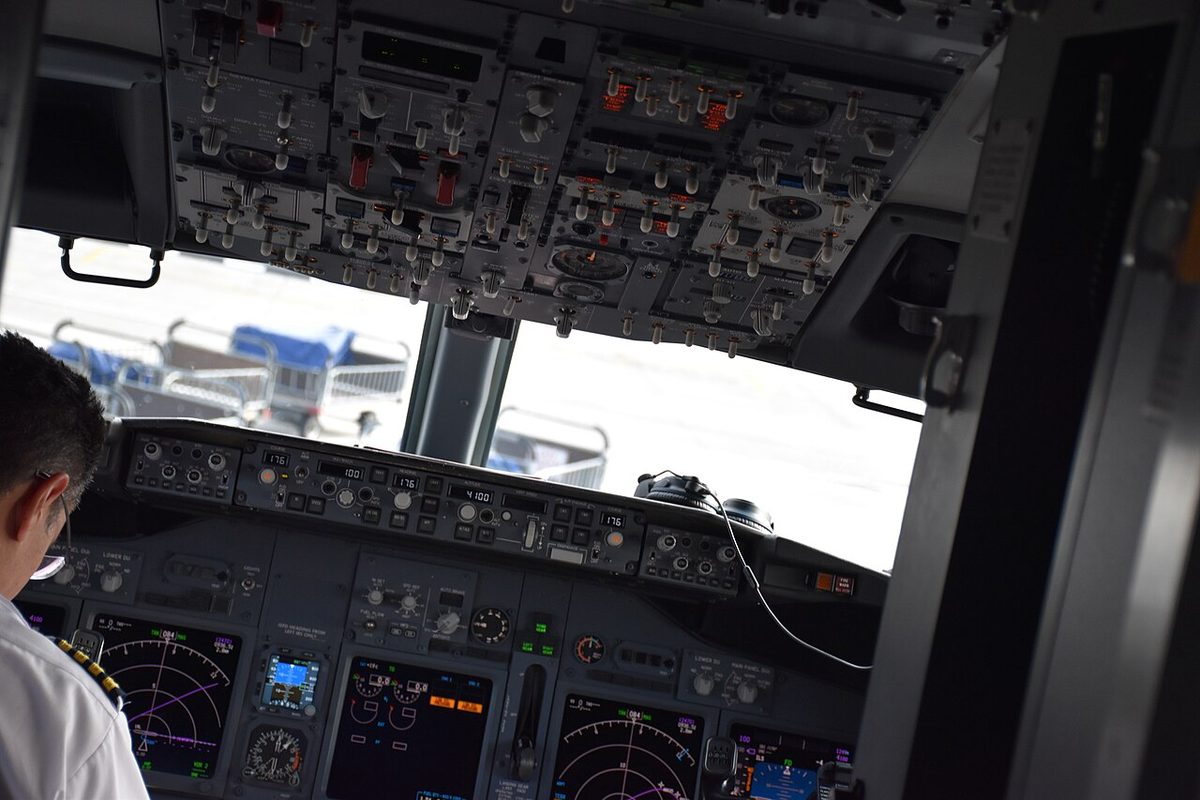
Lateral modes
Lateral modes, which Boeing calls roll modes, steer through the roll channel:
- Heading select (HDG SEL) turns the aircraft to the heading set on the heading bug and holds it. Moving the bug with the mode engaged starts the turn at once, and on the 737 the aircraft turns in the direction the heading selector was rotated.
- Heading hold (HDG HOLD) holds the heading at engagement. The simplest autopilots have only a wing leveller.
- LNAV on Boeing aircraft, NAV on Airbus aircraft, follows the FMS route. The 737 NG engages it within 3 NM of the active leg, or from further out on an intercept heading of 90° or less that meets the leg before its active waypoint. The A320 arms NAV automatically for take-off unless a heading is preset.
- VOR/LOC captures and tracks a VOR radial or a localiser; the heading mode used for the intercept disengages at capture.
- GPS steering (GPSS), in light aircraft, converts the navigator's desired track and turn anticipation into roll commands that the autopilot follows in its heading mode, so it can fly the GPS flight plan with fly-by turns, procedure turns and holds.
The A320's HDG and TRK are called its basic modes because they back up the others: at a flight plan discontinuity, after loss of the flight plan, or when an autopilot is engaged without a flight director. In the United States, AIM 5-5-16 requires pilots flying RNAV 1 departures and arrivals to use a CDI, flight director and/or autopilot in lateral navigation mode.
Vertical modes
Vertical modes, Boeing's pitch modes, control the elevator:
- Altitude hold (ALT HOLD) holds the selected altitude or, if engaged elsewhere, the altitude at which it was engaged. On the 737 a later change of altimeter setting does not move the reference. Altitude hold mode is normally reached through an automatic capture phase, ALT ACQ on the 737 and ALT* on the A320, as the aircraft approaches a selected altitude.
- Vertical speed (V/S) holds the selected rate of climb or descent; on the A320 flight path angle (FPA) holds an angle instead.
- Level change (LVL CHG) on the 737, open climb and open descent (OP CLB, OP DES) on the A320, holds a speed with the elevator while the thrust is fixed at the climb limit or at idle.
- VNAV or the managed climb and descent modes follow the FMS vertical profile.
- Take-off/go-around (TO/GA). On the 737 the take-off pitch command is 10° nose-down until 60 kt, then 15° nose-up; after lift-off it stays at 15° until the climb rate is sufficient and then targets the selected speed plus 20 kt, normally V2 + 20. For a go-around it commands 15° nose-up initially.
The vital question in each vertical mode is who holds the speed:
| Mode | Elevator holds | Thrust holds |
|---|---|---|
| ALT HOLD, altitude capture | Altitude | Speed |
| V/S, FPA | Vertical speed or path angle | Speed |
| G/S | Glideslope | Speed |
| LVL CHG, OP CLB, OP DES | Speed | Climb limit or idle |
Exam tip: V/S flies a rate, not a speed. Climbing in V/S with too little thrust, a basic autopilot with no protection keeps raising the nose until the aircraft approaches the stall. Level change gives up rate of climb instead of speed.
Armed and engaged modes
A mode is armed when it has been selected but its capture conditions are not yet met. LOC is armed while the aircraft flies a heading towards the localiser; G/S is armed until the glideslope is reached. A mode is engaged, or active, when it is controlling the aircraft. The FMA shows both: engaged modes on the top line in green, armed modes on the line below, in white on Boeing aircraft and in cyan (blue) on Airbus aircraft. The step from armed to engaged happens automatically, without any pilot action.
Examples of armed and active modes working together: pressing APP on the 737 or APPR on the A320 arms LOC and G/S; in the A320's CLB mode an altitude mode is always armed; on the 737, with ALT HOLD engaged at the selected altitude, selecting a new altitude more than 100 ft away arms V/S.
The FMA also shows who is flying. On the 737 it reads CMD when an autopilot is engaged in command and FD when only the flight director is on. The A320's fifth column shows the engaged autopilots, the flight directors, such as 1FD2, and the autothrust state. Both manufacturers draw a box around a newly engaged mode for 10 seconds.

The ATPL human performance texts call the belief that the aircraft is in one mode while it is in another a mode error. Their classic example is the Aeroméxico DC-10-30 that entered a prolonged stall buffet over Luxembourg in November 1979 while climbing with vertical speed selected on the autopilot instead of airspeed hold. Airline procedures therefore require every FMA change to be called out and cross-checked by the other pilot.
Localiser and glideslope capture
A coupled ILS approach starts by arming the approach mode, which arms both localizer and glide slope modes (LOC and G/S). Localizer capture, written localiser capture in British usage, comes first: the 737 requires the localiser to be captured before the glideslope, and the heading mode used for the intercept disengages when it is. The A320 can arm LOC only above 400 ft radio altitude.
Glideslope capture normally follows from below. On the 737 it occurs at 2/5 dot below the glideslope. On the A320 altitude hold disengages automatically and G/S engages when the aircraft reaches the capture zone with LOC or LOC engaged and G/S armed. Once the glideslope is captured on the 737, ALT HOLD, V/S and LVL CHG are inhibited; the crew leaves the approach mode by pressing TO/GA, or by disengaging the autopilots and switching both flight directors off.
Light-aircraft autopilots have the same logic in simpler form. NAV mode tracks the localiser laterally but will never capture the glideslope; APR must be selected, and a pilot who watches the aircraft instead of the annunciator may notice only when the glideslope needle reaches full scale.
Warning: capture the glideslope from below. The glide path antenna produces false glideslopes above the real one. In May 2013 a Boeing 737 approaching Eindhoven above the glide path in approach mode pitched up steeply on glideslope capture, and the stick shaker activated before the crew recovered (see ILS).
Mode reversion
Mode reversion is an automatic change of mode without pilot selection, either to protect the flight envelope or because the conditions a mode needs no longer exist.
- Envelope protection. On the 737, if the speed falls to the minimum speed in V/S, the flight director and autopilot revert to LVL CHG, commanding a speed 5 kt above the minimum; reaching a gear, flap or VMO/MMO placard limit makes the system hold a speed slightly short of that limit. On the A320, if an excessive vertical speed selected in a climb brings the speed down to VLS, the target is temporarily disregarded to hold VLS.
- Loss of conditions. On the A320, NAV reverts to HDG or TRK at a flight plan discontinuity, and the vertical mode reverts with it to a selected mode; OP CLB reverts to V/S if the selected altitude is set below the aircraft; and altitude capture reverts to V/S if the selected altitude is changed by more than 250 ft during the capture.
The A320 announces every reversion with a triple click, a box around the new mode for 10 seconds and flight director bars flashing for 10 seconds. Reversions are not universal. The 737 has no minimum speed reversion with the autothrottle off in ALT HOLD or after glideslope capture, and a basic light-aircraft autopilot may have none at all.
Flight director comparator
Airliners have two flight directors, each normally computed by its own computer. On the 737 the computer of the first autopilot engaged in command is the master, and an MA light on the mode control panel shows which one controls the flight director modes. With both F/D switches on and neither autopilot in command, the two flight directors operate independently in an ILS approach with the localiser and glideslope captured, or in a take-off or go-around below 400 ft radio altitude.
The flight director comparator described in the ATPL texts checks the two computations against each other. It removes the command bars if they disagree by more than a few degrees, figures of about 1° to 4° in pitch and 3° to 9° in roll being quoted, and restores them when they agree again. It is active only when both flight directors are on, no autopilot is engaged, take-off/go-around or approach mode is in use and the aircraft is below 800 ft radio altitude: the phases in which a pilot hand-flying the bars most needs to trust them. The A320 shows the state on its FMA: 1FD2 normally, 1FD- if the crew switches flight director 2 off, and 1FD1 if flight director 2 fails, both PFDs then showing the orders of the remaining one.
Frequently asked questions
What is the difference between a flight director and an autopilot?
The flight director computes the attitude needed to follow the selected modes and shows it as command bars; it has no authority over the controls, so the pilot flies the aircraft to the bars. The autopilot moves the controls itself, following the same commands from the same computer. With both engaged the bars show what the autopilot is doing, which is why selecting a wrong mode changes the aircraft's flight path, not just the display.
What is the difference between an armed and an engaged autopilot mode?
An armed mode has been selected but is waiting for its capture conditions, such as reaching the localiser or the selected altitude. An engaged or active mode is controlling the aircraft now. The flight mode annunciator shows engaged modes on its top line in green and armed modes below them, in white on Boeing aircraft and in cyan on Airbus aircraft. The change from armed to engaged happens automatically.
Why does the autopilot not capture the glideslope?
The glideslope is captured only if the approach mode has armed it: on a light-aircraft autopilot NAV mode tracks the localiser laterally but never captures the glideslope, so APR must be selected. Airliner systems also require the localiser to be captured first. Procedures call for intercepting the glideslope from below, because false glideslopes lie only above the real one and a capture from above can produce a steep pitch-up.
What is mode reversion?
Mode reversion is an automatic change to another mode without pilot selection. It protects the flight envelope, for example when a Boeing 737 in vertical speed mode reaches its minimum speed and reverts to level change, or it replaces a mode whose conditions have disappeared, as when the A320's NAV mode reverts to heading at a flight plan discontinuity. The new mode is highlighted on the FMA, and the crew must notice and confirm it.
What is the difference between vertical speed mode and level change?
In vertical speed mode the elevator holds the selected rate of climb or descent and the autothrottle holds the speed, so if thrust is insufficient the speed decays. In level change the elevator holds the speed and the thrust is fixed at the climb limit or at idle, so the rate of climb or descent is whatever results. Level change protects the speed at the expense of the rate; vertical speed protects the rate at the expense of the speed, unless the system has protection.
Test yourself on Flight Director and Autoflight Modes
The v1prep banks cover this topic in Instrumentation (022), with a worked explanation for every answer. EASA ATPL, PPL, IR and CPL, the FAA written tests and A320/B737 type ratings.
Start practising →Sources and further reading
- EASA, Explanatory Note to ED Decision 2018/001/R, Part-FCL theoretical knowledge learning objectives (022 Instrumentation)
- EASA Easy Access Rules for Large Aeroplanes (CS-25), CS 25.1329 and AMC 25.1329, Flight guidance system
- FAA Instrument Flying Handbook (FAA-H-8083-15B), Chapter 5, Flight Instruments (flight support systems)
- FAA Aeronautical Information Manual, Chapter 5 Section 5 (5-5-16, RNAV and RNP operations)
- Dutch Safety Board, Pitch-up Upsets due to ILS False Glide Slope
- NTSB Aircraft Accident Report AAR-80-10, Aeromexico DC-10-30 XA-DUH over Luxembourg, 11 November 1979
Library articles are written for study and exam preparation. They do not replace your aircraft's approved documentation, your operator's procedures or the regulations themselves.