Airbus A220 Fuel and Hydraulic Systems
The A220 carries its fuel in two wing tanks and a centre tank, with boost pumps, centre tank and gravity transfer, and single-point pressure refuelling. Its three hydraulic systems work at 3,000 psi: system 2 has an engine-driven pump and an AC motor pump, system 3 two AC motor pumps, and a power transfer unit (PTU) completes the set.
The Airbus A220 stores its fuel in three tanks, a centre tank and two wing tanks, the wing tanks built of carbon fibre reinforced plastic (CFRP). Left and right boost pumps supply the engines, fuel is moved by two centre tank transfer systems and a gravity transfer path, and the aircraft is refuelled through a single pressure adapter. Its three hydraulic systems, numbered 1, 2 and 3, work at a nominal 3,000 psi and are pressurised by engine-driven and AC motor pumps, with a power transfer unit (PTU).
Both systems are described here from the Transport Canada MMEL, the Airbus Aircraft Characteristics and the type certificates; the flight crew operating manual's schematics are not among these sources, so some details, such as which actuator each hydraulic system feeds, are not given. General principles are covered in fuel tanks, venting and inerting, fuel feed, boost pumps and crossfeed and hydraulic pumps and power sources.
Fuel tanks and capacities
Pressure refuelling fills three tanks: the centre tank and the two wing tanks. The MMEL also refers to collector tanks, each with a water drain valve of its own; six water drain valves are installed, two of them in the centre tank. Three fuel tank pressure relief valves serve the wing and centre tanks, and the fuel venting requirements of ICAO Annex 16, Volume II, apply to the type.
The CFRP wing tanks appear in the certification basis: EASA set special conditions on composite fuel tanks and uncontained engine debris, tyre debris and fuel leakage from CFRP tanks, the fire resistance of CFRP wing fuel tanks, and water and ice in the fuel system. A fuel tank inerting system (FTIS) is fitted, with a dual flow shut-off valve, an inlet isolation valve and a temperature isolation valve.
Usable fuel, as Airbus defines it, is the fuel available for the engines and the APU. For the A220-300, the Airbus Aircraft Characteristics give a maximum fuel tank capacity of 5,681 US gal (21,508 L), and Rücker and Scholz use the same 21,508 L when they compare it with the 26,730 L of the A319neo, 19.5 % less. The A220-100 holds more: TCCA and the FAA list reduced fuel capacity among the A220-300's differences from the A220-100, and increased capacity the other way round. The flight manual of each aircraft is the reference for planning.
Fuel feed, indication and pumps
A left and a right boost pump are installed, and each engine has an inlet fuel pressure switch: with one inoperative, the MMEL allows dispatch, except for extended operations, only with both boost pumps verified working and selected ON for the entire flight, and gravity transfer verified working. An APU fuel feed shut-off valve isolates the APU's supply; if its actuator fails, the valve is secured closed and the APU is considered inoperative.
EICAS shows the quantity in each wing tank and the centre tank and the total. With one tank indication inoperative, the total is no longer displayed. The FUEL synoptic page adds fuel used and the fuel temperature, measured by a sensor in each wing tank. The MMEL's FUEL FAULT messages cover a fuel computer and left wing, right wing and centre wing remote data concentrators (RDCs), each with redundancy, and a low fuel indication is fitted. Each engine has a fuel flow indication; with L or R FUEL FLOW DEGRADED, that engine's fuel flow readout and the fuel used on the synoptic page are considered degraded.
Transfer, balance and no jettison
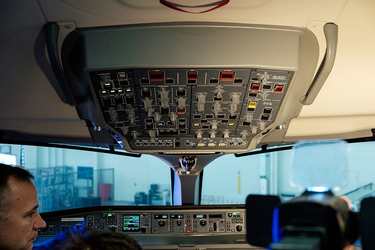
Two centre tank fuel transfer systems move fuel out of the centre tank. With one or both inoperative, the MMEL allows dispatch, except for extended operations, only with the centre tank empty. A gravity transfer shut-off valve is also installed, with a FUEL GRAV XFR switchlight (ON legend) on the overhead FUEL panel. The MMEL also mentions a manual fuel transfer system and a defuel/isolation transfer valve.
Fuel balance must be verified when the indications are degraded: with a wing tank quantity indication inoperative, fuel quantity and balance are verified before each flight, and gravity transfer, manual fuel transfer and both centre tank transfer systems must work. Avionics Build 8.0A2 removed the AUTO fuel transfer status arrow from the EICAS fuel display and the FUEL synoptic page, because it could be shown wrongly under certain failures; the change is mandatory for ETOPS.
The A220 has no fuel jettison system: the FAA lists fuel jettisoning as not applicable to both models because of their design.
Exam tip: no fuel jettison on either A220 model. Centre tank transfer inoperative means a centre tank empty for dispatch.
Refuelling
The refuel/defuel adapter is on the right wing, about 8.3 m from the centreline; a left-wing adapter is optional. The Airbus Aircraft Characteristics give these rates at 50 psi (344.74 kPa) at the adapter:
| Tanks filled | Rate |
|---|---|
| Centre tank and both wing tanks together | 260 US gal/min (984 L/min) |
| Both wing tanks | 140 US gal/min (530 L/min) |
| Centre tank only | 140 US gal/min (530 L/min) |
Three refuel shut-off valves, one per wing tank and one for the centre tank, admit the fuel. The refuel/defuel control panel has fuel quantity displays, a preselected quantity with an automatic mode, a manual mode and a start/stop selector, and some aircraft have a virtual refuel panel in the flight deck. A FUELING DOOR OPEN INFO message monitors the fuelling door.
In cold weather, fuel at 0 °C (32 °F) or below can cause clear ice on the wing even when the outside air temperature is above freezing; with high humidity or visible moisture, Airbus requires a tactile check of the wing surfaces.
Three hydraulic systems
The A220 has three hydraulic systems, each with a nominal pressure of 3,000 psi (206.84 bar). Each has a reservoir with a quantity transducer and a bleed/relief valve, and pressure, return and case drain filters with differential pressure indicators. System 1 has the largest reservoir in every Airbus table, about 5.0 US gal (18.8 L), and system 2 about 4.33 US gal (16.4 L); the tables give different figures for system 3, but always less than system 1.
Accumulators store pressure: systems 1 and 2 each have a maintenance-free accumulator, and system 3 two accumulators with pressure gauges and pressure sensors. The accumulator charging point is at the aft equipment bay door, with gauges reading 0 to 5,000 psig. Each system has fill, pressure and return quick disconnects on the ground servicing panel. System 1 is serviced through an access door on the left of the fuselage, system 2 on the right and system 3 through the aft equipment bay door on the centreline.
The overhead HYD panel has HYD 1 SOV and HYD 2 SOV switchlights with a CLSD legend, and the HYD synoptic page shows the firewall shut-off valve positions with each system's temperature, pressure and quantity.
Pumps and the power transfer unit
| System | Pumps named in the MMEL |
|---|---|
| 1 | Two pump pressure switches; pumps not named |
| 2 | Engine-driven pump EDP 2A, AC motor pump ACMP 2B |
| 3 | AC motor pumps ACMP 3A and ACMP 3B |
Each PW1500G has a drive pad for a hydraulic pump, geared to N2 at 0.1835:1. Four units have a switch with an AUTO position: the power transfer unit (PTU) and ACMP 2B, 3A and 3B. If an AUTO position fails, the MMEL replaces it with ON: the AC motor pump for the entire flight, the PTU before take-off and landing after a check in ON.
Two single-engine taxi provisos in the MMEL involve the PTU and ACMP 2B. With a system 1 pump pressure switch inoperative, the PTU and ACMP 2B are selected ON if the aircraft taxies on the right engine only. With the EDP 2A pressure switch inoperative, ACMP 2B is selected ON for a taxi on the left engine only.
The public sources name few hydraulic users. The landing gear actuation system is one: dispatch with its alternate extension system inoperative requires no external hydraulic leak, the landing gear secured down and the landing gear control valve deactivated. The flight control actuators are called power control units (PCUs), but the sources do not say which hydraulic system feeds each one. The wheel brakes are electric, with 16 electric motor actuators (EMAs) and 8 EMA controllers, and the MMEL lists no hydraulic brake components.
Failure cases
The hydraulic messages in the sources include the HYD PUMP 3A FAIL and HYD PUMP 3B FAIL cautions, HYD PUMP 2B FAIL and HYD PTU FAIL, and the dual-system cautions HYD 1-3 LO PRESS and HYD 2-3 LO PRESS. To dispatch with HYD PUMP 3A FAIL, ACMP 3A is deactivated, no PUMP 3B, PUMP 2B or PTU fault may be present, and ACMP 3B runs continuously in flight and stays ON for landing.
Since Build 8.0A2, after a HYD 1-3 LO PRESS caution with the flaps at 0 or 1, the SLAT/FLAP lever is set to 2 for landing, so that it does not have to move for a go-around; the fly-by-wire normal mode 2.20 update modified both dual-system procedures again. For training a zero-flap or zero-slat approach in the aircraft, TCCA forbids depressurising hydraulic systems to create the failure.
On the fuel side, dispatch with the centre tank quantity indication inoperative requires the centre tank to be empty and not refuelled, and a centre tank refuel shut-off valve failed closed makes centre tank refuelling impossible.
Frequently asked questions
How much fuel does the A220 carry?
The Airbus Aircraft Characteristics give the A220-300 a maximum fuel tank capacity of 5,681 US gal (21,508 L), the figure Rücker and Scholz also use: 19.5 % less than the 26,730 L of the A319neo. The A220-100 holds more fuel than the A220-300: TCCA and the FAA list reduced fuel capacity among the A220-300's differences. The flight manual of each aircraft is the reference for planning.
Can the A220 jettison fuel?
No. The FAA Flight Standardization Board report lists fuel jettisoning among the regulatory training items that do not apply to the A220-100 and A220-300 because of the aircraft's design. An early return at high weight therefore cannot be preceded by dumping fuel.
How many hydraulic systems does the A220 have?
Three, numbered 1, 2 and 3, each working at a nominal 3,000 psi (206.84 bar). System 2 is pressurised by engine-driven pump EDP 2A and AC motor pump ACMP 2B, system 3 by two AC motor pumps, ACMP 3A and 3B. A power transfer unit (PTU) and maintenance-free accumulators on systems 1 and 2 complete the installation; system 3 has two accumulators with pressure gauges.
What does the AUTO position of the A220 hydraulic pump switches do?
Four hydraulic units have a switch with an AUTO position: the PTU and the AC motor pumps ACMP 2B, 3A and 3B. If an AUTO position fails, the MMEL replaces it with ON: an AC motor pump is then selected ON for the entire flight, and the PTU is checked working in ON before each flight and selected ON before take-off and landing. No engine-driven pump switch is listed.
Where is the A220 refuelled and how fast?
Through a single pressure refuel/defuel adapter on the right wing; a left-wing adapter is optional. At 50 psi the Airbus Aircraft Characteristics give 260 US gal/min (984 L/min) when the centre tank and both wing tanks are filled together, and 140 US gal/min (530 L/min) for the two wing tanks or the centre tank alone. Refuelling is controlled in automatic mode with a preselected quantity or in manual mode.
Test yourself on Airbus A220 Fuel and Hydraulic Systems
The v1prep banks cover this topic in the A220 type-rating bank, with a worked explanation for every answer. EASA ATPL, PPL, IR and CPL, the FAA written tests and A320/B737 type ratings.
Start practising →Sources and further reading
- Transport Canada, Master Minimum Equipment List BD-500 (A220-100/-300), Issue 015
- Airbus, A220 Aircraft Characteristics Publication (ACP), BD500-3AB48-13800-00
- EASA Type-Certificate Data Sheet EASA.IM.A.570, BD-500 (A220-100 and A220-300), Issue 25
- EASA Type-Certificate Data Sheet IM.E.090, Pratt & Whitney PW1500G series engines
- Transport Canada, Operational Evaluation Report BD-500 (A220-100 and A220-300), Revision 3
- FAA Flight Standardization Board Report, Airbus Canada (formerly Bombardier) BD-500-1A10/-1A11 (A220-100/-300), Revision 3 (draft)
- J. Rücker and D. Scholz, Highlights of the Airbus A220 from a Pilot's Perspective, HAW Hamburg, 2024
Library articles are written for study and exam preparation. They do not replace your aircraft's approved documentation, your operator's procedures or the regulations themselves.