Airbus A220 Electrical System
The A220 electrical system generates AC power with two engine-driven variable frequency generators (VFGs) and an APU generator, accepts 115 V, 400 Hz external AC power on the ground, converts AC to DC in three transformer rectifier units, and has two batteries and a generator driven by a ram air turbine (RAT).
The Airbus A220 generates its electrical power with two variable frequency generators (VFGs), one on each engine, backed by a generator on the auxiliary power unit (APU), a generator driven by a ram air turbine (RAT) and two batteries. On the ground it takes 115 V, 400 Hz AC power from a ground power unit; there is no connection for DC ground power. Three transformer rectifier units (TRUs) supply the DC network, and the distribution includes three electrical power centres (EPCs) and two bus power control units (BPCUs).
The public documents used here, the Transport Canada MMEL, the Airbus Aircraft Characteristics and the engine type certificate, do not show which load sits on which bus. They do show how the system is built and what backs up what, which is what a type-rating candidate is asked. The general principles are covered in electrical power distribution, aircraft batteries and generator control and protection.
Power sources
| Source | Where | Main parts (MMEL) |
|---|---|---|
| L GEN, R GEN | One VFG on each PW1500G engine | VFG, generator control unit (GCU), overvoltage protection unit (OPU), generator line contactor (GLC), line current transformer (LCT), control switch |
| APU GEN | Honeywell 131-9(C) APU | APU generator (AGEN), APU generator control unit (AGCU), OPU3, APU line contactor (ALC), LCT3 |
| External AC power | Receptacle behind access door 115DL, left side, about 3.6 m aft of the nose | External line contactor (ELC), external power current transformer assembly (EPCTA) |
| RAT GEN | Ram air turbine | Deployed sensor, heaters A and B, guarded RAT GEN switch |
| BATT 1, BATT 2 | Two batteries | Charger, heater, temperature sensor and battery line contactor (BLC) on battery system 1 |
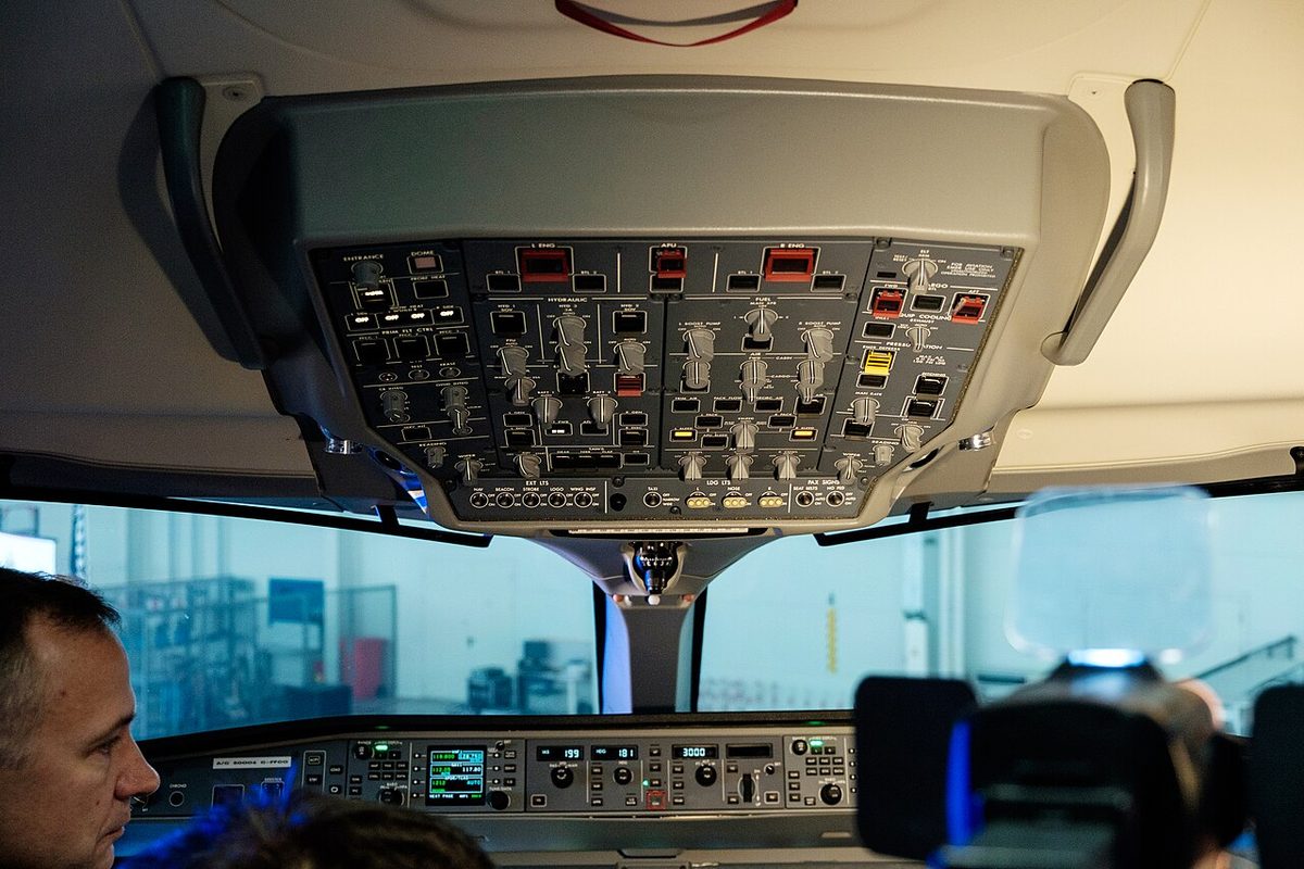
The overhead panel carries the corresponding pushbutton annunciators: L GEN, R GEN and APU GEN, each with FAIL and OFF legends; EXT PWR with AVAIL and IN USE; RAT GEN with an ON light; the guarded L DISC and R DISC switches with OIL and DISC legends; and CABIN PWR. The L GEN FAIL, R GEN FAIL and APU GEN FAIL messages are cautions.
Variable frequency generators
The engine type certificate lists two aircraft accessory drive pads on each PW1500G, both geared to N2, the high-pressure spool: a hydraulic pump pad at 0.1835:1 and a generator pad at 0.8595:1, which the certificate labels for an integrated drive generator (IDG). The A220 MMEL calls the generators themselves VFGs; none of the public sources describes the generator drive further or gives the output frequency.
Each VFG has its own oil system. A remote oil level sensor (ROLS) on each generator monitors the oil level, and the L GEN OIL LO LEVEL and R GEN OIL LO LEVEL INFO messages report a low level. A VFG with low oil pressure or high oil temperature is treated as inoperative: before dispatch the MMEL requires it to be selected OFF, its oil drained and the generator disconnected.
That disconnection uses a remotely activated disconnect on each generator, controlled by the guarded L DISC and R DISC switches on the overhead panel. Their legends read OIL and DISC. A missing guard on one of these switches is acceptable for dispatch only if the opposite VFG works.
The MMEL notes link each engine generator with an AC bus. With a low oil level on the left VFG, the APU generator must be verified able to supply AC BUS 1 before each flight; with a low level on the right VFG, AC BUS 2.
Exam tip: the A220's engine generators are variable frequency generators. Each has its own oil system with a remote oil level sensor and a remotely activated disconnect, selected with the guarded L DISC or R DISC switch.
APU generator and external power
The APU generator can stand in for an engine generator. Except for extended operations (ETOPS), the MMEL allows dispatch with one VFG system inoperative provided the failed VFG is selected OFF, the APU is started before departure and run throughout the flight, and all EPCs, all TRUs and the opposite VFG are verified working. The APU remains available as an electrical source when its bleed air valve is inoperative, and it can normally be started on battery power: the MMEL warns that battery APU start may be inoperative with BPCU 2 degraded.
External power is AC only. The Airbus Aircraft Characteristics set these requirements:
| Parameter | Requirement or protection limit |
|---|---|
| Voltage and frequency | 115 ±5 V, 400 ±15 Hz |
| Undervoltage | 107 ±2 V (lowest phase) or 108.5 ±2 V (three-phase average), 4.5 s |
| Redundant overvoltage | 130 ±3.3 V (highest phase), 0.75 s |
| Overfrequency, underfrequency | 418 ±2 Hz, 4.5 s; 382 ±2 Hz, 4 s |
| Phase sequence | A-B-C, 0.1 s |
| Ground power unit | 75 kVA or more; 60 kVA can cause EICAS nuisance messages |
When a ground power unit is plugged in, AVAIL lights come on both on the cockpit electrical panel and on the electrical/towing service panel. Power reaches the aircraft only when the crew selects EXT PWR ON: BPCU 1 then energises the external line contactor, and it also protects the aircraft systems from poor ground power. External AC can power the whole AC network or only the buses that supply the passenger cabin.
Airbus warns against any interruption just after power-up. Critical systems such as fly-by-wire and electrical then run their power-up built-in test (PBIT), and a ground power unit dropping off line or delivering poor power can interrupt it and latch failures that need maintenance action, with possible delays or cancellations.
Distribution, TRUs and essential buses
The MMEL names three electrical power centres (EPC 1, EPC 2 and EPC 3), each with an EPC DEGRADED INFO message, bus tie contactors BTC 1, BTC 2 and BTC 3 and DC tie contactors (DTCs). Its notes reveal some of the paths: with EPC 1 degraded and BTC 1 inoperative, the APU generator cannot supply AC BUS 1, and external power can supply neither AC BUS 1 nor AC BUS 2.
Three transformer rectifier units, TRU 1, TRU 2 and TRU 3, convert AC to DC. TRU 1 and TRU 2 each connect through a TRU line contactor (TLC 1 and TLC 2). With TRU 1 or TRU 2 inoperative, dispatch requires TRU 3 and the remaining TRU working, both VFG systems and all EPCs.
Essential buses exist: TCCA's list of failures that degrade anti-icing names DC ESS BUS 2, and the landing gear system has GEAR FAULT messages for 28V ESS and 28V NORM redundancy loss. Each engine's electronic control has an aircraft 28 V DC backup supply to each of its two channels. The public sources do not say which loads each bus carries.
The MMEL mentions cockpit thermal circuit breakers (TCBs) with a status indication and INFO messages for the left and right CB panels, and the CB TRIP advisory reports a tripped breaker. Two electrical units named after the fly-by-wire system, the L and R FBW PC, are each associated with a permanent magnet generator (PMG). The MMEL also lists CDC units 1 to 5 with power supply modules: with a CDC 3 power supply module inoperative the left thrust reverser is considered inoperative, and with a CDC 4 module the right one.
Batteries
The A220 has two batteries. Battery system 1 comprises battery 1, its charger, heater and temperature sensor and battery line contactor BLC 1; a battery system 2 is also installed. EASA's certification basis includes special conditions on lithium battery installations. The electrical/towing service panel has a BATT annunciator light; the MMEL notes that without it the battery may run down if not selected OFF.
Battery-only operation on the ground is kept short. With battery system 1 inoperative, the MMEL asks crews to limit battery-only ground operation to keep battery 2 fully charged, and with the APU fire warning horn inoperative it limits battery-only power to 5 minutes.
Ram air turbine and emergency power
The ram air turbine sits in the electrical chapter of the MMEL. It drives a generator: the overhead RAT GEN pushbutton, under a guard, shows ON, and a sensor monitors whether the RAT is deployed. Two heaters, A and B, have their own INFO messages. None of the public sources lists a RAT-driven hydraulic pump; on the A320, by contrast, the RAT drives a hydraulic pump that in turn drives the emergency generator.
The sources also name an EMER PWR ONLY warning: Build 8.0A2 masks several air system advisories while it is displayed, and Build 8.0A3 suppresses the equipment bay smoke detection messages with it. Dispatch with EPC 3 degraded requires the RAT to be verified not deployed and the APU to run throughout the flight.

Failure cases and the MMEL
The main MMEL reliefs show what backs up what:
| Failure for dispatch | Main conditions |
|---|---|
| One VFG system | VFG OFF, APU running throughout the flight, all EPCs and TRUs and the other VFG working |
| APU generator system | Both VFG systems working, APU GEN selected OFF |
| VFG oil low level (INFO message) | Both VFGs working, APU GEN verified able to supply the affected AC bus, oil serviced within 12 flight hours |
| TRU 1 or TRU 2 | TRU 3 and the other TRU, both VFGs and all EPCs working |
| Battery system 1 | Charger and heater deactivated, BATT 1 OFF, BLC 1 open, forward cargo door actuator considered inoperative, APU running with APU GEN ON |
| External power system | APU generator working normally, external power not used |
All these reliefs except the last exclude extended operations (ETOPS).
The MMEL asks for the APU to run throughout the flight in other cases too: with flight control computer PFCC 3 deactivated, for example, or with EPC 2 degraded in some configurations. In flight, a generator failure posts a GEN FAIL caution, and a DC ESS BUS 2 failure is one of those whose procedure gained an ice dispersal step with Build 8.0A2.
Frequently asked questions
What generators does the A220 have?
Two engine-driven variable frequency generators (VFGs), L GEN and R GEN, one on each PW1500G engine; an APU generator on the Honeywell 131-9(C) APU; and a generator driven by the ram air turbine (RAT). On the ground the aircraft also accepts 115 V, 400 Hz external AC power. Each VFG system has its own control unit, overvoltage protection unit, line contactor and oil system with a remote oil level sensor.
Can the A220 use DC ground power?
No. The Airbus Aircraft Characteristics state that the external power system takes AC power from a ground cart and that there is no provision for DC ground power. The supply must be 115 V plus or minus 5 V at 400 Hz plus or minus 15 Hz. Airbus recommends a ground power unit of 75 kVA or more, as a 60 kVA unit can trigger EICAS nuisance messages.
What does the A220 ram air turbine power?
The public sources show the RAT as part of the electrical system. The MMEL lists it in its electrical power chapter, with a deployed sensor, two heaters (A and B) and a RAT GEN pushbutton with an ON light under a guard on the overhead panel. None of the sources lists a hydraulic pump driven by the RAT, so it should not be assumed to drive a hydraulic pump as the A320's does.
What happens when an A220 engine generator fails?
The L GEN FAIL or R GEN FAIL caution appears. The APU generator can take over: the MMEL allows dispatch, except for extended operations, with one VFG inoperative provided it is selected OFF, the APU is started before departure and runs throughout the flight, and all electrical power centres, all three TRUs and the other VFG are verified working.
How many TRUs and batteries does the A220 have?
Three transformer rectifier units, TRU 1, TRU 2 and TRU 3, convert AC to DC, each connected through a TRU line contactor. With TRU 1 or TRU 2 inoperative the MMEL requires TRU 3 and the remaining TRU to be working. There are two batteries; battery system 1 includes battery 1, its charger, heater, temperature sensor and battery line contactor, and the APU can be started on battery power.
Test yourself on Airbus A220 Electrical System
The v1prep banks cover this topic in the A220 type-rating bank, with a worked explanation for every answer. EASA ATPL, PPL, IR and CPL, the FAA written tests and A320/B737 type ratings.
Start practising →Sources and further reading
- Transport Canada, Master Minimum Equipment List BD-500 (A220-100/-300), Issue 015
- Airbus, A220 Aircraft Characteristics Publication (ACP), BD500-3AB48-13800-00
- EASA Type-Certificate Data Sheet IM.E.090, Pratt & Whitney PW1500G series engines
- EASA Type-Certificate Data Sheet EASA.IM.A.570, BD-500 (A220-100 and A220-300), Issue 25
- Transport Canada, Operational Evaluation Report BD-500 (A220-100 and A220-300), Revision 3
- FAA Flight Standardization Board Report, Airbus Canada (formerly Bombardier) BD-500-1A10/-1A11 (A220-100/-300), Revision 3 (draft)
Library articles are written for study and exam preparation. They do not replace your aircraft's approved documentation, your operator's procedures or the regulations themselves.