Approach Speeds and Go-Around Climb Requirements
The reference landing speed VREF is the speed at 50 ft above the threshold on which landing distances are based; the final approach speed VAPP adds margins for wind, gusts and ice. Approach climb and landing climb requirements ensure that the aeroplane can climb away from an approach or a baulked landing.
The approach is flown to a speed chosen with care. Too slow, and a gust, windshear or a late flare leaves too little margin above the stall. Too fast, and the aeroplane floats, touches down long and needs more runway than the flight manual assumed. The reference landing speed (VREF) is the anchor: the speed over the threshold on which landing distances are based. The final approach speed (VAPP) adds margins for the day's wind, gusts and ice.
Behind the speeds sit two climb requirements that decide whether the aeroplane can abandon the landing. The approach climb covers a go-around with one engine inoperative, the landing climb a baulked landing close to the runway with all engines operating. On a hot or high aerodrome either can limit the landing mass, and PANS-OPS adds a third gradient, for the missed approach procedure itself.
Reference landing speed VREF
For large aeroplanes certified under CS-25 and 14 CFR Part 25, VREF is the speed in the landing configuration at which the aeroplane crosses 50 ft above the threshold in the certified landing distance. It may not be less than 1.23 VSR0, where VSR0 is the 1 g reference stall speed in the landing configuration, nor less than VMCL, the minimum control speed in the landing configuration (see minimum control speeds). Older certification bases and textbooks use 1.3 VS0, based on the lower minimum speed seen in a stall manoeuvre. For EASA performance Class B aeroplanes, single and multi-engine, VREF is at least 1.3 VS0.
Flight manual landing distances assume the aeroplane crosses the 50 ft point at exactly VREF. VREF depends on mass and flap setting:
- Mass. Stall speed, and so VREF, varies with the square root of mass, so a 10 % change in landing weight changes VREF by about 5 %. Speeds are recalculated whenever the landing mass changes, and a gross error in the entered weight corrupts every speed.
- Flap. More flap lowers VSR0 and therefore VREF. The A320's VREF is 1.23 VS in CONF FULL; the 737 publishes VREF30 and VREF40 for its two normal landing flap settings.
- Altitude. As an indicated airspeed VREF does not change with altitude, but the true airspeed and ground speed at a high or hot aerodrome are higher, so the landing distance is longer.
Speed carried beyond VREF costs runway. Kinetic energy rises with the square of speed, so the FAA notes that 10 % excess speed at the threshold adds roughly 20 % to the landing distance. ATPL texts give about 200 ft for every 5 kt above VREF (see landing distance).
Final approach speed VAPP
The final approach speed (VAPP), VAP on Embraer types, is the speed flown on final. It is VREF, or on Airbus types VLS, the lowest selectable speed, plus an approach speed additive. The additive gives a margin against the speed losses of gusts and windshear near the ground and some room for speed control with the autothrust engaged. Manufacturers build it differently:
| Type | Final approach speed |
|---|---|
| Airbus A320 (FMS) | VLS + the higher of 5 kt and one third of the tower headwind component; wind correction limited to 15 kt |
| Embraer E190-E2 | VREF + half the steady headwind + the gust increment; total additive 5 to 20 kt |
| Boeing 737 | Command speed VREF30 or VREF40 + wind additives |
The wind additive is based on the headwind component, not the total wind; on the A320 a tailwind adds nothing beyond the 5 kt minimum. The gust factor, or gust increment, is the difference between the gust value and the steady wind speed. On the E190-E2 it is added in full, while only half the steady headwind is.
On the A320, VAPP may not be less than VLS + 5 kt during an autoland, with autothrust engaged, with ice accretion, or in a gusty crosswind above 20 kt, and in strong or gusty crosswinds the crew may raise the increment up to 15 kt. The A320's ground speed mini function then adjusts the managed target during the approach: it flies VAPP plus the difference between the current headwind and the tower headwind, bounded by VAPP and VFE NEXT. The ground speed therefore never falls below the value expected at VAPP in the tower wind, and the aeroplane keeps its energy if the headwind dies away near the ground.
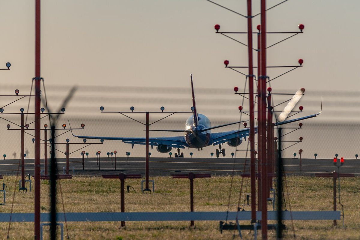
The ice speed additive accounts for the higher stall speed of an airframe carrying ice. The 737 procedure calls for a raised reference speed, VREF ICE, when engine anti-ice will be used during landing, when wing anti-ice has been used at any time during the flight, or when icing conditions were met and the landing temperature is below 10 °C. With VREF ICE the wind additive should not exceed 5 kt, and the flight management computer does not adjust its displayed VREF automatically. On the E190-E2 the approach increment is also applied for ice, low visibility and autoland.
The additives do not change the stabilised approach window. Under the Flight Safety Foundation criteria the aeroplane is stabilised when its speed is between VREF and VREF + 20 kt, among other conditions (see stabilised approach).
Threshold speed and approach categories
A separate speed decides how much protected airspace an instrument approach needs. VAT, the threshold speed used for approach categories, is the indicated airspeed at the threshold equal to 1.3 VS0 or 1.23 VS1G in the landing configuration at maximum certificated landing mass. The FAA uses VREF, or 1.3 VSO where no VREF is specified.
| Category | VAT |
|---|---|
| A | Below 91 kt |
| B | 91 to 120 kt |
| C | 121 to 140 kt |
| D | 141 to 165 kt |
| E | 166 to 210 kt |
Because it is based on the maximum certificated landing mass, the category is a property of the aircraft, not of the day: an aeroplane landing lighter keeps its category and simply flies to more conservative minima. The FAA's Flight Standardization Board places the A318, A319 and A320 in Category C and the A321 in C or D, depending on the model's certified landing weight. An aircraft manoeuvring faster than its category's speeds, as when circling, uses the minima of the higher category (see obstacle clearance and approach minima).
Approach climb and landing climb requirements
CS-25 and Part 25 require two go-around cases, both at the aerodrome's pressure altitude and temperature:
| Requirement | Rule | Engines | Configuration and speed | Minimum gradient |
|---|---|---|---|---|
| Approach climb | 25.121(d) | Critical engine inoperative, others at go-around thrust | Gear up, approach flap; climb speed from normal landing procedures but not above 1.4 VSR | 2.1 % twin, 2.4 % three engines, 2.7 % four |
| Landing climb | 25.119 | All engines, at the thrust available 8 s after the levers move from minimum flight idle | Landing configuration, gear down; speed VREF | 3.2 % |
The approach climb represents a discontinued approach with one engine inoperative. The approach flap setting used must have a stall speed no more than 110 % of the landing configuration's. The landing climb represents the baulked landing, a go-around from close to the runway with everything still extended. Its 8-second allowance reflects the time an engine takes to accelerate from idle towards go-around thrust.
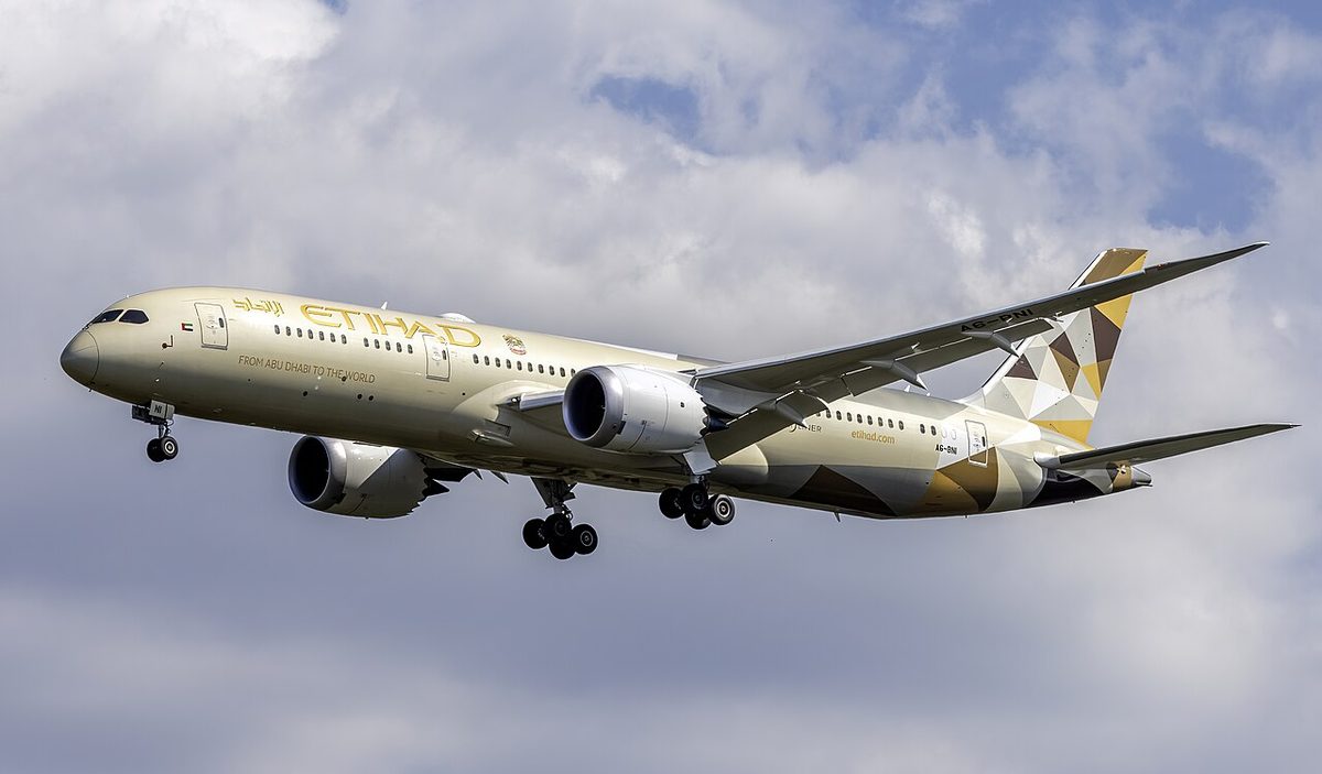
The certification assumption that an all-engines go-around always climbs at least as well as a one-engine-inoperative one has been challenged by newer thrust management. Where a reduced go-around thrust mode is fitted, such as Airbus's Soft GA, a special condition (B-12) requires the published approach climb performance to be the lower of the two cases, or a clear alert when the reduced thrust would give the lower gradient.
The same gradients reach into systems design. Under CS 25.1001 a fuel jettison system must be installed unless the aeroplane can meet both requirements at maximum take-off mass less the fuel for a 15-minute flight comprising a take-off, go-around and landing.
For EASA Class B multi-engine aeroplanes the exam figures are lower: a baulked landing gradient of 2.5 % with all engines, gear down, landing flap and speed VREF, using the power available 8 seconds after the levers are moved; and 0.75 % at 1,500 ft above the landing surface with one engine inoperative, its propeller feathered and gear and flap retracted.
Missed approach climb gradient
The certification gradients prove the aeroplane; the missed approach climb gradient belongs to the procedure. PANS-OPS assumes a nominal missed approach gradient of 2.5 %. AIP France explains how that works in practice: obstacle clearance is checked with 2.5 %, minima for it are always published, and lower minima for steeper gradients are published beside their gradient. A gradient of 3.3 % is used to check separation from other tracks and airspace, so 3.3 % must be flown unless a greater one is published. The FAA requires at least 200 ft per nautical mile, about 3.3 %, unless the chart specifies more; at 120 kt ground speed that is 400 ft/min.
Operators must also allow for an engine failure during the missed approach. Under EU-OPS 1.510, still examined, an approach with a decision height below 200 ft needed a one-engine-inoperative missed approach gradient of at least 2.5 %, or the published gradient if greater. The Nice ILS Y RWY 04L shows the effect: its minima are split between a 2.5 % and a 3 % missed approach, and a Category C aeroplane able to hold 3 % on one engine may use the lower 3 % line, DA 310 ft (300 ft) with RVR 1,400 m, instead of 390 ft (380 ft) with 1,700 m (see go-around and missed approach).
Landing climb limit mass
Class A operators determine the maximum landing mass as the lowest of three limits: the structural maximum landing mass, the field-length limited mass, from the landing distance with the regulatory factors applied, and the landing climb limit mass, the highest mass at which the approach and landing climb gradients can be met at the expected aerodrome conditions. The climb limit falls as pressure altitude and temperature rise, because thrust falls, so it is most often the binding limit at hot and high aerodromes.
If the planned landing mass exceeds the landing climb limit mass, the flight cannot be dispatched as planned. The remedies are to reduce the mass, by carrying less payload or less fuel with a closer alternate, to use a flap setting with less drag where the flight manual provides one, which improves the gradient but raises VREF and the landing distance, or to plan for another aerodrome.
Frequently asked questions
What is the difference between VREF and VAPP?
VREF is the reference landing speed for the aeroplane's mass and landing flap setting, the speed at 50 ft over the threshold assumed in the flight manual landing distance. For large aeroplanes it is at least 1.23 times the reference stall speed and at least VMCL. VAPP, the final approach speed, is VREF or the Airbus VLS plus additives for wind, gusts, ice or autothrust, to protect against speed losses on final.
How is the approach speed wind additive calculated?
It depends on the manufacturer. On the E190-E2, VAP is VREF plus half the steady headwind plus the gust increment, the additive being at least 5 and at most 20 kt. On the A320, the FMS sets VAPP as VLS plus one third of the tower headwind or plus 5 kt, whichever is higher, with the wind correction limited to 15 kt. The flight manual or operator procedures always take precedence.
What are the approach climb and landing climb gradients?
Under CS 25.121(d) and 14 CFR 25.121(d), the approach climb requires a gradient of at least 2.1 per cent for a twin, 2.4 for three engines and 2.7 for four, with one engine inoperative, gear up and approach flap. Under 25.119, the landing climb requires 3.2 per cent with all engines, in the landing configuration, using the thrust available 8 seconds after the levers are moved from flight idle.
How is an aircraft's approach category determined?
By VAT, the threshold speed at maximum certificated landing mass in the landing configuration: 1.3 VS0 or 1.23 VS1G. Category A is below 91 kt, B 91 to 120 kt, C 121 to 140 kt, D 141 to 165 kt and E 166 to 210 kt. The FAA uses VREF, or 1.3 VSO. The category does not change with the day's mass, but an aircraft circling faster than its category's speeds uses higher-category minima.
Why can the landing climb requirement limit landing mass?
The approach and landing climb gradients must be achievable at the aerodrome's pressure altitude and temperature. On a hot or high aerodrome engine thrust falls, so the gradient available at a given mass may drop below the requirement. The maximum landing mass is then the landing climb limit mass rather than the structural or field-length limit, and the crew must reduce mass, choose less flap where the flight manual allows it, or plan for another aerodrome.
Test yourself on Approach Speeds and Go-Around Climb Requirements
The v1prep banks cover this topic in Performance (032), with a worked explanation for every answer. EASA ATPL, PPL, IR and CPL, the FAA written tests and A320/B737 type ratings.
Start practising →Sources and further reading
- EASA Easy Access Rules for Large Aeroplanes (CS-25), CS 25.119, 25.121 and 25.125
- 14 CFR 25.125, Landing
- 14 CFR 25.121, Climb, one-engine-inoperative
- EASA Easy Access Rules for Air Operations (Regulation (EU) No 965/2012), CAT.POL.A
- AIP France, ENR 1.5, Holding, Approach and Departure Procedures (aircraft categories, missed approach gradient)
- 14 CFR 97.3, Symbols and terms used in procedures
- FAA AC 91-79B, Aircraft Landing Performance and Runway Excursion Mitigation
Library articles are written for study and exam preparation. They do not replace your aircraft's approved documentation, your operator's procedures or the regulations themselves.