Autopilot
An autopilot is the part of the automatic flight control system that moves the flight controls through servos to hold or change the aircraft's attitude and flight path. It stabilises the aircraft in an inner control loop and follows the modes selected by the pilot through an outer loop.
An autopilot (AP) flies the aircraft by moving its flight controls through servos. At its simplest it holds the wings level; in an airliner it holds or changes heading, altitude, vertical speed, speed and flight path, follows radio beams and the flight management system's route, and on suitably equipped aircraft lands the aeroplane. It does this with the same principle throughout: a closed control loop that measures what the aircraft is doing, compares it with what is wanted and moves the controls to remove the difference.
For the pilot the autopilot is a workload tool with limits. Its authority, its engagement conditions and its failure modes are set by design, and the pilot must know them to use it safely and to take over when it fails. The modes that the pilot selects, and the flight director that shares them, are covered in flight director and autoflight modes.
Autoflight system overview
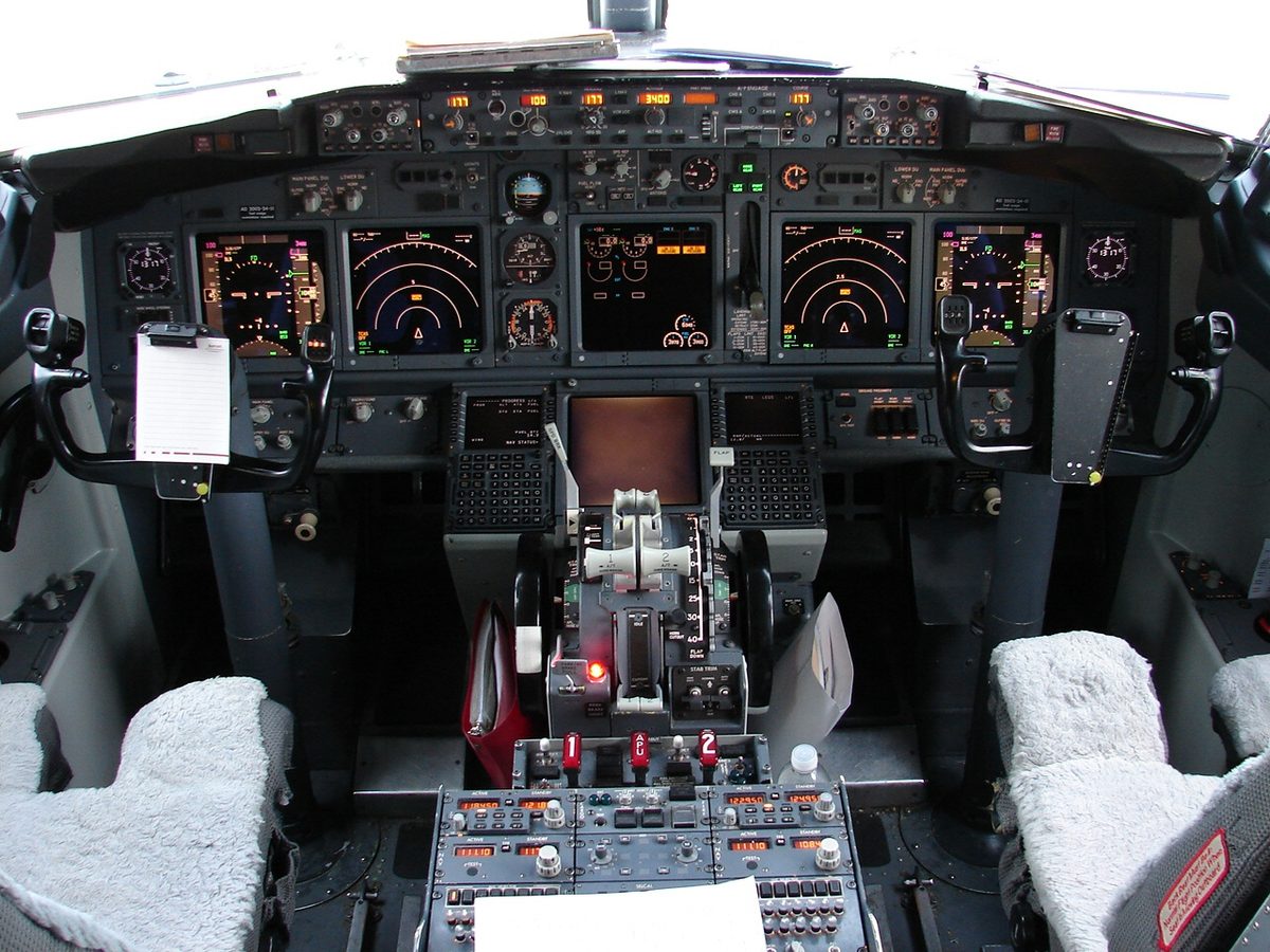
The automatic flight control system (AFCS), also called the auto flight system (AFS) or autoflight system, groups the functions that fly the aircraft automatically: the autopilot, which moves the controls; the flight director, which computes and displays the same commands for a pilot flying by hand; the autothrottle, which controls thrust; and on many aircraft the yaw damper and automatic trim. The names follow the manufacturer. On the Boeing 737 the AFS consists of the autopilot flight director system (AFDS) and the autothrottle, and the AFDS is two flight control computers (FCCs) with a single mode control panel. On the A320 the flight guidance part of each flight management and guidance computer issues the autopilot, flight director and autothrust commands. Digital systems of this kind are also known as a digital flight guidance system (DFGS).
Operating rules build on the autopilot. In European commercial air transport, CAT.IDE.A.135 of Regulation (EU) No 965/2012 requires an aeroplane operated under IFR with a single pilot to be equipped with an autopilot with at least altitude hold and heading mode.
Autopilot channels and axes
An autopilot controls the aircraft through autopilot channels, one per axis:
- Roll is the primary axis, worked through the ailerons. A single-axis autopilot controls roll only and is often called a wing leveller: it holds the wings level and, in more capable units, tracks a heading. It gives no altitude protection.
- Pitch is the secondary axis, worked through the elevator and trim. Roll plus pitch makes a two-axis autopilot, the minimum for altitude hold and heading mode.
- Yaw is the third axis, worked through the rudder, for turn coordination and yaw damping. A three-axis autopilot is needed for automatic landing, where the rudder aligns the aircraft with the runway.
The word channel is also used for a complete, independent autopilot. A single-channel autopilot has one computer and one set of servos; a dual-channel installation has two, which can be engaged together. On the Boeing 737 only one autopilot can be engaged at a time except in approach mode, where both are engaged for an automatic landing, the second by 800 ft radio altitude. Redundant channels that monitor each other are what make fail-passive and fail-operational automatic landings possible (see autoland).
Inner and outer control loops
A closed-loop control system measures its own output and feeds it back to compare with the input; an open-loop system acts on a fixed programme with no feedback. A heating system with a thermostat is closed loop, a heating timer open loop. A servomechanism is a closed-loop system in which a small input controls a much larger output in strict proportion, which is exactly what an autopilot does with the control surfaces.
The autopilot inner loop provides stabilisation. A sensor, a rate gyro in the classic description, detects a disturbance about one axis; a transducer turns it into an electrical signal; the computer compares it with the demand and commands the servomotor; the servomotor moves the control surface; and the aircraft's resulting motion is sensed again by the gyro. This aerodynamic feedback closes the loop, and the surface deflection reduces as the disturbance is corrected. A position feedback from the servo tells the computer where the surface actually is.
The autopilot outer loop provides guidance. It compares the flight path with the target selected by the pilot, such as a heading, an altitude, a radio course or the FMS route, and injects an attitude demand into the inner loop, which responds as if the aircraft had been disturbed. Altitude hold, for example, compares the air data altitude with the target and asks the inner loop for a small pitch change. Modes such as HDG and ALT are outer-loop functions.
Timing matters as much as direction. A correction that arrives late adds to the next swing instead of opposing it, so a yaw damper, for example, uses phase advance, a signal shaping that brings the correction forward so that it acts when the disturbance is at its maximum.
Servos and actuators
An autopilot servo turns the computer's command into movement. Servomotors may be electromechanical, electrohydraulic or pneumatic. On the Boeing 737 the flight control computers command pitch and roll hydraulic servos supplied by two separate hydraulic systems.
Actuators are connected in one of two ways:
- Parallel actuators act alongside the pilot's control run and move the surface and the pilot's control together, so the pilot can see and feel what the autopilot is doing.
- Series actuators are inserted in the control run and move the surface without moving the pilot's control.
A torque limiter or slipping clutch protects the servo drive. It prevents rapid control deflections from imposing excessive structural loads and, if a servo runs away, stops it forcing the surface to full deflection: above the set torque the drive slips or disengages, so that it can be overpowered.
Gain scheduling
The gain of a control loop is how much correction it applies for a given error. No single gain suits every condition, so the autopilot changes it, a process called autopilot gain adaption or gain scheduling.
- Speed. A control deflection that is gentle at low speed can overstress the aircraft at high speed. An input of dynamic pressure from the air data computer reduces the autopilot's authority in proportion to it.
- Approach. A beam gives angular guidance, so a fixed error in degrees means less and less distance as the runway approaches. 1° of glideslope error is roughly 100 ft for every nautical mile from the glide path antenna: more than 600 ft at 6 NM but only about 50 ft at 0.5 NM. With a fixed gain the autopilot would overcontrol near the ground, so the gain is reduced progressively during the approach. Early systems triggered the change by time after glideslope capture, later ones by marker beacons; modern systems use the radio altimeter, which gives a gradual change tied to the actual height.
- Limits. Pitch and bank limits are reduced in sensitive phases. The ATPL texts give an example of the bank limit falling to 30° when tracking a VOR or localiser and to about 15° in the final stages of an automatic landing.
Engagement interlocks and synchronisation
Autopilot interlocks are the conditions that must all be satisfied before the autopilot can engage, and that must remain satisfied to keep it engaged: power supplies, valid attitude and air data, serviceable servos and computers. If any monitored item fails, the autopilot disengages with visual and aural warnings. Some interlocks involve the pilot: the Boeing 737 autopilot will not engage in command or CWS unless no force is being applied to the control wheel and the stabiliser trim autopilot cutout switch is at NORMAL. The A320 autopilot cannot be engaged until the aircraft has been airborne for 5 seconds, and once engaged it locks both sidesticks in neutral.
Synchronisation prevents a snatch on engagement. Before the autopilot engages, synchronising circuits sense any standing signal in the pitch and roll channels and wash it out, so the servos start from the attitude the aircraft already has. That only covers small residuals. The aircraft should be trimmed and stable before engagement, because otherwise the servo takes over an out-of-trim force at engagement and hands it back to the pilot at disconnection.
Automatic pitch trim keeps the aircraft in trim while the autopilot is engaged, and only then. It senses a sustained load on the pitch servo, or its displacement, and trims to remove it, on jets by moving the stabiliser, so the elevator keeps its full authority in both directions and the aircraft is in trim at disconnection. Operating the manual pitch trim with the autopilot engaged disconnects the autopilot on most systems, including the 737's control wheel trim switches. Mach trim is separate: it works whether or not the autopilot is engaged.
Control wheel steering (CWS) lets the pilot manoeuvre through force transducers in the control column without disengaging the autopilot, which holds the new attitude on release. In the system described in the ATPL texts, if the bank is 6° or less when the wheel is released, the autopilot rolls the wings level and holds the heading. Touch control steering (TCS) is different: pressing and holding its button on the control wheel disengages the servos so the pilot can fly by hand. What follows on release depends on the type; on the Embraer E190-E2 the autopilot takes over again and, in its altitude mode, holds the altitude at the moment of release.
Yaw damper and Dutch roll filter
Swept-wing jets are prone to Dutch roll, a coupled yawing and rolling oscillation that appears when the dihedral effect is strong compared with directional stability. Its aerodynamic damping falls with altitude, because at the higher true airspeed a yaw disturbance changes the fin's angle of attack less (see lateral and directional stability).
The yaw damper senses yaw rate, with a rate gyro or from the inertial reference system, and applies small, rapid rudder deflections that stop the oscillation before it builds up. It normally operates throughout the flight, independently of the autopilot, and on many aircraft also helps with turn coordination, runway alignment during an automatic landing and engine failure. Its rudder authority is deliberately small, typically quoted as 3° to 6°, which limits the effect of a yaw damper runaway; where two dampers drive one rudder their authority adds.
A rate gyro responds to every yaw, including a deliberate turn, so the signal passes through a Dutch roll filter, a narrow band-pass filter tuned to the Dutch roll frequency. In a steady turn the yaw rate is constant and the filter output falls to zero, so the damper does not oppose the turn; only the oscillating yaw rate of Dutch roll gets through. Phase advance makes the rudder correction coincide with the maximum yaw rate.
If the yaw damper fails, the flight manual or MEL typically limits the altitude, since damping improves at lower true airspeeds. Any Dutch roll is damped with small, well-timed aileron inputs; rudder inputs tend to lag the motion and can make it diverge.
Servo runaway and protection
A servo runaway (hard-over) is a failure in which a servo drives its surface towards full deflection without command. Designers limit the consequences in layers: torque limiters and deliberately small authority, as in yaw dampers; comparison between channels, which disengages the autopilot when they disagree; and warnings that tell the crew at once.
The pilot's part is to recognise the uncommanded motion and act before the forces build up: hold the controls firmly, press the autopilot and trim disconnect switch, isolate the system with the stabiliser trim cutout switches or circuit breakers as the flight manual directs, and retrim manually.
Warning: in IMC an uncommanded pitch trim movement with the autopilot engaged is an emergency. Restrain the controls and disconnect first; diagnose afterwards.
The height an aircraft can lose before the crew recovers from a malfunction sets the minimum use height of the autopilot. In the United States, 14 CFR 121.579 forbids Part 121 operators to use the autopilot en route, including climb and descent, below the greatest of 500 ft above the terrain, twice the altitude loss that the Airplane Flight Manual specifies for an autopilot malfunction in cruise, and any altitude set by the FAA. Flight manuals add phase-specific figures. The Boeing 737 autopilot may not be engaged below 400 ft AGL after take-off, and under its FAA limitations a single-channel autopilot must be disengaged by 50 ft AGL on an approach. On the A320 the minimum after take-off is 100 ft AGL and at least 5 seconds after lift-off, and 500 ft AGL in phases for which no other figure is given.
Frequently asked questions
What is the difference between the inner loop and the outer loop of an autopilot?
The inner loop stabilises the aircraft: it senses disturbances in attitude and moves the controls to hold the aircraft steady, with the resulting motion fed back to its sensors. The outer loop provides guidance: it compares the flight path with what the pilot has selected, such as a heading, an altitude or a radio course, and feeds attitude demands into the inner loop. Modes such as HDG or ALT are outer-loop functions.
What is the difference between series and parallel autopilot actuators?
A parallel actuator is connected alongside the pilot's control run, so it moves the control surface and the pilot's control column or wheel together; the pilot can see and feel what the autopilot is doing. A series actuator is inserted in the control run and moves the surface without moving the pilot's controls. Either kind drives through a torque limiter, so that a runaway can be overpowered.
What does a yaw damper do?
A yaw damper senses yaw rate, with a rate gyro or from the inertial reference system, and applies small, rapid rudder movements that stop Dutch roll before it builds up. A band-pass filter tuned to the Dutch roll frequency stops it opposing normal turns. Swept-wing jets need it most at high altitude, where aerodynamic damping is weakest; if it fails, the aircraft may have to descend and the pilot damps any oscillation with aileron, not rudder.
What is autopilot gain scheduling?
Gain is how much control the autopilot applies for a given error. Gain scheduling, or gain adaption, changes it with the flight conditions: authority is reduced at high dynamic pressure so the autopilot cannot overstress the aircraft, and reduced progressively on an ILS approach, usually triggered by the radio altimeter, because one degree of beam error means much less distance close to the runway. Bank limits also shrink in the final stages of an automatic landing.
What should a pilot do if the autopilot or pitch trim runs away?
Fly the aircraft first: hold the controls firmly against the uncommanded motion, then disconnect the autopilot and electric trim with the disconnect switch. Isolate the system as the flight manual says, with the trim cutout switches or circuit breakers, and retrim manually. Delaying lets out-of-trim forces build up, which is why autopilot minimum use heights are based on the height lost after a malfunction.
What is control wheel steering?
Control wheel steering (CWS) lets the pilot manoeuvre the aircraft through force transducers in the control column without disengaging the autopilot. The autopilot moves the controls in proportion to the pilot's input and holds the new attitude when the controls are released; in the system described in the ATPL texts, if the bank is 6 degrees or less on release, it rolls the wings level and holds the heading. Touch control steering instead disengages the servos while its button is held.
Test yourself on Autopilot
The v1prep banks cover this topic in Instrumentation (022), with a worked explanation for every answer. EASA ATPL, PPL, IR and CPL, the FAA written tests and A320/B737 type ratings.
Start practising →Sources and further reading
- EASA, Explanatory Note to ED Decision 2018/001/R, Part-FCL theoretical knowledge learning objectives (022 Instrumentation)
- EASA Easy Access Rules for Large Aeroplanes (CS-25), CS 25.1329 and AMC 25.1329, Flight guidance system
- EASA Easy Access Rules for Air Operations (Regulation (EU) No 965/2012), CAT.IDE.A.135
- 14 CFR 121.579, Minimum altitudes for use of autopilot
- FAA Instrument Flying Handbook (FAA-H-8083-15B), Chapter 5, Flight Instruments (flight support systems)
Library articles are written for study and exam preparation. They do not replace your aircraft's approved documentation, your operator's procedures or the regulations themselves.