Vertical Speed Indicator
The vertical speed indicator (VSI) shows an aircraft's rate of climb or descent, normally in feet per minute. It senses the rate of change of static pressure by comparing the pressure inside a capsule with the pressure in the instrument case, which follows only slowly through a calibrated leak.
The vertical speed indicator (VSI) shows how fast an aircraft is climbing or descending, usually in feet per minute. European texts also call it the rate of climb and descent indicator (RCDI). It needs no power and no pitot pressure: like the altimeter, it works on static pressure alone, but instead of the pressure itself it measures how quickly that pressure is changing.
The VSI is a support instrument rather than a primary one. It shows the direction of a vertical change at once and the rate of change after a short delay, which makes it invaluable for levelling off smoothly, flying a constant rate of descent on an approach and noticing a slow drift away from an assigned level. Its limitations, above all its lag, explain why pilots confirm with the altimeter before trusting it.
VSI principle
Inside the airtight case is a thin metal capsule. Static pressure from the pitot-static system is fed directly into the capsule and, at the same time, into the case around it through a restriction called the metering unit, choke or calibrated leak.
In level flight the static pressure is steady, the pressures inside and outside the capsule are equal and the needle rests on zero. When the aircraft starts to climb, static pressure falls. The capsule sees the lower pressure immediately, but the case pressure can only fall as fast as air leaks out through the metering unit, so it stays slightly higher. The higher case pressure squeezes the capsule, and a linkage turns that movement into a climb indication. In a descent the sense reverses. Once a steady rate is established, the pressure difference across the leak settles at a value proportional to the rate of change of static pressure, which the scale presents as feet per minute.
This is the VSI principle: the instrument measures a pressure difference that exists only while static pressure is changing. When the aircraft levels off, the leak equalises the two pressures and the needle returns to zero.
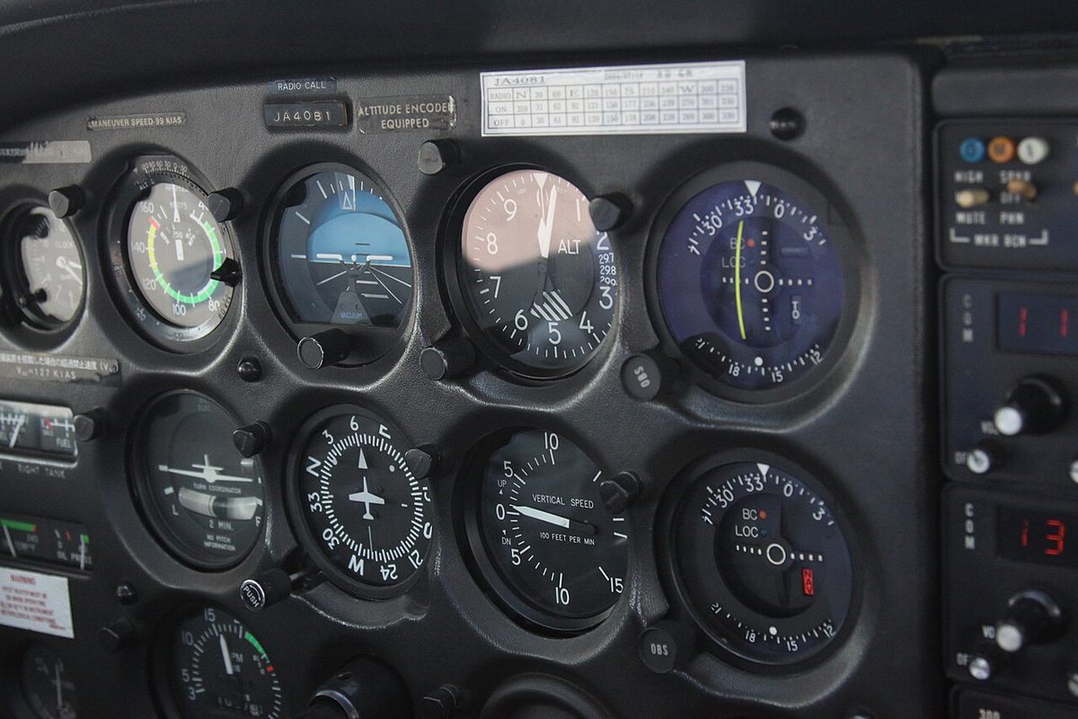
Scales are either linear or logarithmic. A logarithmic scale spreads the low rates, typically up to about 1,000 ft/min, over most of its length and compresses the high rates at the ends, which gives the fine resolution needed for levelling off and for holding a constant descent on an approach. Because its marks are not evenly spaced, a logarithmic scale must be read from its graduations rather than by eye between the numbers.
Metering unit and calibrated leak
A given rate of climb produces a smaller rate of pressure change in thin air than near sea level, because each hectopascal spans more feet higher up. A single simple hole would therefore make the VSI under-read at altitude. The VSI metering unit overcomes this by combining two kinds of restriction: a capillary tube, in which the flow is viscous and dominates at small pressure differences, and a sharp-edged orifice, in which the flow is turbulent and dominates at larger ones. Their different characteristics compensate each other, so that a given rate of climb gives nearly the same reading at any altitude within the instrument's range.
Many VSIs also have a zeroing screw, used on the ground to set the needle to zero, and diaphragm overload stops that limit the movement of the capsule so that an extreme rate, in a dive recovery or severe turbulence, cannot damage it.
Lag and errors
Lag is built into the principle. After a change of pitch the needle moves at once in the right direction, but a stable pressure difference across the leak takes several seconds to develop. The FAA's Instrument Flying Handbook puts the time for the rate to stabilise at about 6 to 9 seconds; European ATPL texts speak of a few seconds. The same delay appears at level-off: the needle takes a few seconds to return to zero, the more so after a long climb at a high rate. A VSI still showing a climb while the altimeter has stopped moving is therefore normal lag, not a fault.
The VSI also carries the usual pressure instrument errors:
- Instrument error, from manufacturing tolerances and friction in the mechanism.
- Position error, when the pressure at the static vents changes with airspeed rather than height. It is most noticeable during the take-off run, when the VSI may briefly show a climb or descent while the aircraft is still on the runway.
- Manoeuvre-induced error, a short-lived false rate during rapid pitch or roll changes, caused by pressure fluctuations at the static vents and by the inertia of the linkage.
Blockages have characteristic effects. A pitot blockage has none, because the VSI uses no pitot pressure. A static blockage traps the pressure in both capsule and case, so the needle returns to zero and stays there; combined with an altimeter that freezes while the aircraft is still climbing or descending, it is a reliable diagnostic. Selecting a cabin alternate static source in an unpressurised aircraft makes the VSI show a brief climb, as the cabin pressure is slightly lower, before it settles. Breaking the VSI glass, the last resort the FAA describes for aircraft without an alternate static source, lets cabin air into the static system; it will most likely leave the VSI itself unusable, and its indications are then ignored.
Instantaneous VSI (IVSI)
The instantaneous vertical speed indicator (IVSI) removes most of the lag by adding an accelerometer unit, also called a dashpot or vertical acceleration pump. It consists of small pistons, held centrally by springs in vertical cylinders and connected into the instrument's pressure lines. When the aircraft starts to climb or descend, the pistons lag behind the vertical acceleration because of their inertia, and their movement pumps air to create an immediate pressure difference in the correct sense. As the steady rate becomes established, the springs recentre the pistons and the normal metering unit takes over.
The IVSI is more sensitive than a basic VSI, and that brings its own errors:
- In turbulence it over-reacts, and small needle excursions should be ignored.
- In a steep level turn the increased load factor makes the pistons sink in their cylinders exactly as an upward acceleration would, so the IVSI shows a false climb while the altimeter stays steady.
Exam tip: a basic VSI lags; an IVSI does not, but it shows a false climb in a steep level turn and exaggerates turbulence. Both read zero with the static source blocked, and neither is affected by a pitot blockage.
Vertical speed on electronic displays
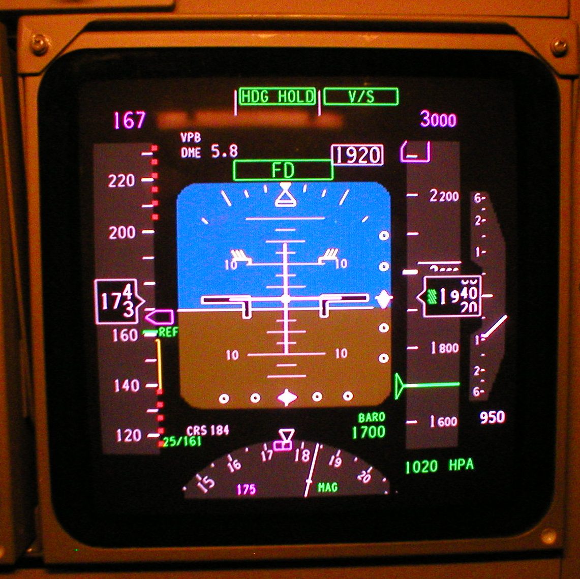
On aircraft with air data computers, vertical speed is computed electronically and shown as a pointer on a scale beside the altitude tape, often non-linear like a logarithmic dial. On the Boeing 737 a digital readout appears when the rate exceeds 400 ft/min, above the scale in a climb and below it in a descent. The same scale shows TCAS resolution advisories on some variants: the band of vertical speeds to avoid is shown in red, and the pilot flies the pointer out of it (see ACAS/TCAS). Because electronic vertical speed comes from the air data computer, it is lost with it. In a light aircraft glass cockpit an air data computer failure removes the vertical speed scale along with the speed and altitude tapes, and on the A320 vertical speed is no longer displayed once the crew has switched off all three air data references and flies on the backup speed scale (see air data computer).
In the FAA's primary and supporting method of instrument flying, the VSI is the primary instrument for pitch in a constant-rate climb or descent, while the altimeter remains the reference for holding a level. A useful cross-check on an approach: a 3° path descends about 318 ft per nautical mile, and a rate of descent of about five times the groundspeed in knots keeps the aircraft on it, so about 450 ft/min at 90 kt and 700 ft/min at 140 kt. Rates also give times: at 1,500 ft/min, a descent from FL120 to FL60 takes four minutes.
Cabin vertical speed indicator
A pressurised aircraft carries a second VSI for the cabin. The cabin vertical speed indicator, or cabin rate of climb indicator, works on the same principle but senses cabin pressure, and shows how fast the cabin pressure altitude is changing. Together with the cabin altimeter and the differential pressure gauge it forms the minimum set of pressurisation indications, and 14 CFR 25.841 and CS 25.841 require the crew to have indications of cabin altitude and of its rate of change, without setting a maximum rate.
In normal operation the pressurisation controller makes the cabin climb in proportion to the aircraft, but far more slowly. Typical comfort values are about 500 ft/min in the climb and about 300 ft/min in the descent, slower going down because ears equalise less easily as pressure rises. Before descent the crew sets, or the flight management system supplies, the landing elevation, and the controller schedules the cabin descent so that it reaches field pressure by landing. On the A320, the automatic system allows up to 750 ft/min cabin descent, and the ECAM cabin pressure page makes the cabin vertical speed flash when it reaches 1,750 ft/min.
A cabin climbing when it should not be is one of the earliest cues of a pressurisation fault, often visible before any warning. How cabin altitude and rate are controlled is covered under pressurisation, and the response to a loss of pressure under decompression.
Frequently asked questions
How does a vertical speed indicator work?
Static pressure is fed straight into a capsule inside the VSI, and into the surrounding case through a restriction called the metering unit or calibrated leak. In level flight the two pressures are equal and the needle reads zero. In a climb or descent the case pressure lags behind the changing capsule pressure, and the difference, which is proportional to the rate of change of static pressure, deflects the capsule and moves the needle.
Why does the vertical speed indicator lag?
The VSI works by letting air leak slowly into its case, so a stable pressure difference takes time to build up after a change of attitude and time to die away after a level-off. The needle moves in the correct direction at once, but the FAA's Instrument Flying Handbook says the rate itself takes about 6 to 9 seconds to stabilise. For that reason the VSI is read as a trend and the altimeter confirms the level.
What happens to the VSI if the static port is blocked?
With the static source blocked, the pressure in the capsule and in the case stays at the value trapped at the moment of blockage, so no pressure difference can develop and the VSI returns to zero whatever the aircraft does. Together with an altimeter that has stopped moving while the aircraft is still climbing or descending, a VSI stuck at zero is a classic sign of a static blockage.
What is an instantaneous vertical speed indicator?
An instantaneous vertical speed indicator, or IVSI, adds an accelerometer unit, small spring-loaded pistons in cylinders, to the normal VSI. At the start of a climb or descent the pistons move under vertical acceleration and create an immediate pressure difference, so the needle responds without the usual delay. The price is extra sensitivity: an IVSI over-reacts in turbulence and shows a false climb in a steep level turn.
What does the cabin vertical speed indicator show?
In a pressurised aircraft the cabin vertical speed indicator shows how fast the cabin pressure altitude is changing, in feet per minute. The pressurisation controller normally keeps the cabin rate far below the aircraft's own rate, typically about 500 ft/min in the climb and about 300 ft/min in the descent, for passenger comfort. An unexpected cabin climb can be the first sign of a pressurisation fault.
Test yourself on Vertical Speed Indicator
The v1prep banks cover this topic in Instrumentation (022), with a worked explanation for every answer. EASA ATPL, PPL, IR and CPL, the FAA written tests and A320/B737 type ratings.
Start practising →Sources and further reading
- FAA Pilot's Handbook of Aeronautical Knowledge (FAA-H-8083-25), Chapter 8, Flight Instruments
- FAA Instrument Flying Handbook (FAA-H-8083-15B), Chapter 5, Flight Instruments
- 14 CFR 25.841, Pressurized cabins
- EASA Easy Access Rules for Large Aeroplanes (CS-25)
- EASA, Explanatory Note to ED Decision 2018/001/R, Part-FCL theoretical knowledge learning objectives (022 Instrumentation)
Library articles are written for study and exam preparation. They do not replace your aircraft's approved documentation, your operator's procedures or the regulations themselves.