Operational Flight Plan
The operational flight plan (OFP) is the operator's plan for the safe conduct of a flight, based on the aeroplane's performance, its operating limitations and the conditions expected on the route and at the aerodromes. It sets out the route, levels, times and fuel, and is used in flight as the navigation and fuel log.
Before a commercial flight departs, the crew receive a document that describes the flight they are about to make: the route and its waypoints, the levels, the forecast winds and temperatures, the time and fuel planned for every leg, the alternates and the fuel figures that the rules require. This is the operational flight plan (OFP). It is not the same as the ATC flight plan, which tells air traffic services what the aircraft intends to do. The OFP is the operator's own plan, and in flight it is the record against which the crew check that the aircraft is doing what was planned.
Private pilots keep the same kind of record on a smaller scale, the pilot's navigation log. Whether produced by a computer or by hand, the plan is only as good as the data behind it, and its value comes from comparing it with what actually happens.
Purpose of the OFP
ICAO Annex 6 describes the operational flight plan as the operator's plan for the safe conduct of the flight, based on the aeroplane's performance, its other operating limitations and the conditions expected on the route and at the aerodromes. In EASA commercial air transport it is one of the documents carried for each flight, along with the technical log, the ATS flight plan, NOTAM and meteorological information and the mass and balance documentation. The planning department usually produces it, but the commander signs it, accepting the plan and taking ownership of it. It then serves as the main briefing reference for the flight and cabin crew. The OFP, with the NOTAM briefing and the mass and balance documentation, is kept for at least 3 months after the flight.
A typical OFP contains:
- the aircraft, flight number, date and crew;
- the departure, destination and alternate aerodromes, with the planned times;
- the route, waypoint by waypoint, with tracks, distances, levels, forecast wind and temperature, groundspeeds and times for each leg;
- the planned fuel remaining at each waypoint and the fuel breakdown: taxi, trip, contingency, alternate, final reserve, additional and extra fuel (see fuel planning and fuel reserves);
- en-route alternates and, on remote or ETOPS routes, the equal time points between them;
- space to record the actual times, fuel and clearances in flight.
Exam tip: the OFP is signed by the commander, not by the planner, and it is kept for 3 months. EASA exam questions also expect the OFP to be listed among the documents carried on each flight.
Computer flight plans
Airlines produce OFPs with flight planning systems, and the result is usually called a computer flight plan (CFP). The system combines the aircraft's performance model, the planned mass, the cost index and gridded global forecasts of wind and temperature at many levels to compute the route, levels, speeds, times and fuel. It can compare many routes to find the least-cost or minimum-time option (see cost index and cruise economics) and work out the equal time points on remote routes. CFP tracks are commonly given in degrees true, the reference in which upper winds are forecast.
A CFP can still be wrong, usually because of wrong input data. Before accepting it the crew check that:
- it uses the latest forecasts;
- the fuel and time figures are plausible for the route and season;
- the tracks and distances look sensible and the route agrees with the ATC flight plan and the expected clearance;
- the alternates are appropriate;
- the planned cruise method, cost index or long range cruise for example, is the correct one;
- the planned masses agree with the load sheet.
The pilot's navigation log
The pilot's navigation log (PLOG) is the hand-prepared equivalent used for VFR and light-aircraft IFR flights. Its columns follow the order of the calculation: for each leg the safety altitude, planned level, TAS, forecast wind, true track, drift and true heading, variation and magnetic heading, groundspeed, distance, time and fuel, with columns for the estimated and actual times over each point. Winds aloft are forecast in degrees true, so the wind triangle is solved with true tracks and the heading converted to magnetic at the end (see triangle of velocities). The TAS comes from the planned indicated airspeed, corrected first to calibrated airspeed and then for pressure altitude and temperature on the navigation computer.
In flight the log becomes a check. Actual times over each point give the groundspeed achieved, the revised estimates and the fuel check (see in-flight fuel management). Even with GNSS on board the log keeps the pilot in the loop, so that a receiver failure does not leave the pilot without a plan (see dead reckoning and visual navigation).
Company routes
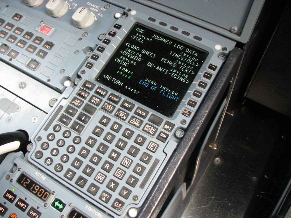
A company route (CO RTE) is an airline's standard route between two aerodromes, stored under an identifier in the navigation database of the flight management system along with the airways, procedures and waypoints. Instead of typing every waypoint, the crew call up the route by its name, on the A320 from the INIT page, and add the departure and arrival procedures. Company routes save time and reduce keying errors, but they are only a starting point. The loaded route is checked waypoint by waypoint against the OFP and the ATC clearance, because the route planned for the day may differ from the stored one. The navigation database is updated on a 28-day cycle, so a stored route can also be overtaken by changes to airways and waypoints.
Time estimates: ETD, ETE and ETA
Three estimates link the plan to the clock:
- Estimated time of departure (ETD): when the flight is expected to leave. In the ICAO flight plan the departure time is filed as the estimated off-block time (EOBT) in Item 13, the time the aircraft is expected to start moving for departure.
- Estimated time en route (ETE): the planned flight time, as the FAA calls it. The ICAO flight plan gives the total estimated elapsed time (EET) in Item 16, counted from take-off to the point where the instrument approach is expected to begin for an IFR flight, or to overhead the destination when no such point exists.
- Estimated time of arrival (ETA): the departure time plus the time en route.
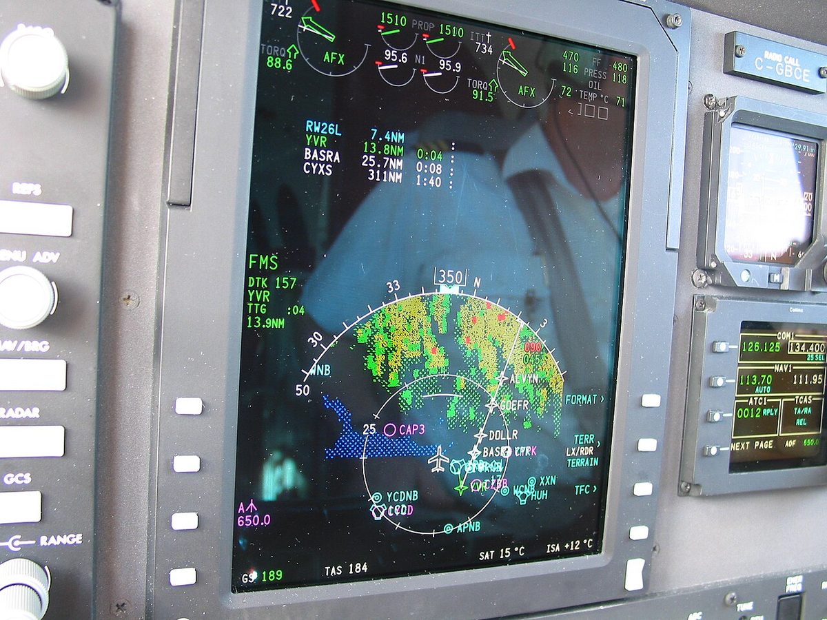
In flight the ETA is revised from the groundspeed actually achieved. Crossing a VOR at 10:12 and a point 30 NM further on at 10:24 gives 150 kt; the remaining 70 NM to the destination will take 28 minutes, so the revised ETA is 10:52. On the ground, a controlled flight delayed more than 30 minutes beyond its EOBT, or an uncontrolled one delayed more than 1 hour, must have its flight plan amended or cancelled and refiled; within the Eurocontrol IFPS area a delay message is needed once the delay exceeds 15 minutes. The ETA also anchors the weather assessment: EASA planning rules test the destination forecast over the period from 1 hour before to 1 hour after it.
Terrain escape planning
An engine failure or a loss of pressurisation forces a descent, and over high ground the plan must show that the descent can be made safely. Operators plan this route by route (see one-engine-inoperative en-route performance).
Driftdown escape routes. After an engine failure in the cruise, a multi-engine aeroplane drifts down at the one-engine-inoperative speed to the highest level it can hold on the remaining engines. EASA's en-route rule for performance Class A aeroplanes, CAT.POL.A.215, carried over from EU-OPS, allows two ways of planning for this. Either the one-engine-inoperative net flight path has a positive gradient at least 1,000 ft above all terrain and obstacles within 5 NM (9.3 km) either side of the intended track, or it clears all terrain on the way to a suitable aerodrome by at least 2,000 ft, with a positive gradient at 1,500 ft above the aerodrome where the landing is assumed. The FAA's 121.191 has the same structure, with 5 statute miles either side of track. Where the second method is used, the operator publishes driftdown escape routes: a decision point, a turn towards lower terrain and the aerodrome to fly to.
Decompression escape. After a loss of pressurisation the crew descend to 10,000 ft, or to the minimum safe altitude if that is higher. Chemical passenger oxygen generators last only about 12 to 22 minutes, so over mountainous terrain the route is planned with escape paths that bring the aircraft down to a safe level before the passenger oxygen runs out.
Glide range circle method. A single-engine aeroplane cannot drift down. Under the commercial rules for single-engine Class B aeroplanes it must, after an engine failure, be able to reach a place where a safe forced landing can be made. In planning, the pilot marks suitable forced-landing areas on the chart and draws around each a circle whose radius is the glide range from the planned cruise altitude: height divided by the glide gradient. From 10,000 ft with a 7 per cent gradient the still-air glide range is about 23.5 NM; from 15,000 ft, about 35 NM. The route and level are chosen so that the circles cover the whole route, with an allowance for the headwind that shortens the glide. Where the gaps between suitable areas are too large, the route must change or the aircraft must fly higher.
Dispatch release and weather package
Who authorises the flight depends on the system of operational control, the authority over the initiation, continuation, diversion or termination of a flight. ICAO Annex 6 allows the operator to delegate responsibility for it only to the commander and, where the operator's approved method of supervision requires one, to a flight operations officer or dispatcher (see operational control and flight dispatch).
In US airline operations the dispatcher shares the responsibility. For domestic and flag operations under Part 121, each flight needs a dispatch release signed by the pilot in command and an aircraft dispatcher, who are jointly responsible for the preflight planning, delay and release of the flight. Under 121.687 the release contains the aircraft identification and trip number, the departure, intermediate, destination and alternate airports, the type of operation, the minimum fuel supply and the latest weather reports and forecasts, or a statement that they are attached. A flight may be released under IFR only if the reports and forecasts show the destination at or above the authorised minimums at the estimated time of arrival. Supplemental operations use a flight release instead. The dispatcher monitors the flight and may amend the release en route.
The dispatch weather package, or briefing package, travels with the OFP. It normally holds METARs and TAFs for the departure, destination and alternate aerodromes, SIGMETs, significant weather and upper wind charts, and NOTAMs for the aerodromes and route (see meteorological services and briefings). When dangerous goods are carried, the commander also receives written notice of them. The commander reads the package against the OFP: a TAF amended since the plan was made, or a NOTAM closing an alternate, can invalidate the fuel figures and the choice of alternate as surely as a wrong wind.
Frequently asked questions
What is an operational flight plan?
An operational flight plan is the operator's plan for a particular flight. It gives the route waypoint by waypoint, the levels, forecast winds and temperatures, the planned times and fuel for each leg, the alternates and the required fuel figures. The commander signs it before departure, carries it on board and uses it in flight to record actual times and fuel against the plan.
What is the difference between the OFP and the ATC flight plan?
The ATC flight plan tells air traffic services what the aircraft intends to do: its identification, equipment, route, level, speed, times and alternates in a standard ICAO format. The operational flight plan is the operator's own detailed plan, with leg-by-leg winds, times and fuel, used by the crew to conduct and monitor the flight. The two must describe the same route.
What should a crew check before accepting a computer flight plan?
A computer flight plan is only as good as its input data. The crew check that it uses the latest forecasts, that the fuel and time figures are plausible for the route and season, that tracks, distances and the route agree with the ATC flight plan, that the alternates are suitable and that the planned cruise method and mass are the correct ones.
What does a Part 121 dispatch release contain?
Under 14 CFR 121.687 a dispatch release contains the aircraft identification and trip number, the departure, intermediate, destination and alternate airports, the type of operation, IFR or VFR, the minimum fuel supply and, for domestic and flag operations, the latest weather reports and forecasts or a statement that they are attached. The dispatcher and the pilot in command both sign it.
What is a driftdown escape route?
A driftdown escape route is a pre-planned path to follow if an engine fails over high terrain. From a published decision point the crew turn towards lower ground and descend at the one-engine-inoperative speed to a level the aircraft can hold, reaching a suitable aerodrome while clearing the terrain by the required margin. Operators publish such routes where the terrain would otherwise limit the aircraft's mass.
Test yourself on Operational Flight Plan
The v1prep banks cover this topic in Flight Planning (033), with a worked explanation for every answer. EASA ATPL, PPL, IR and CPL, the FAA written tests and A320/B737 type ratings.
Start practising →Sources and further reading
- ICAO Annex 6, Operation of Aircraft, Part I, International Commercial Air Transport, Aeroplanes
- EASA Easy Access Rules for Air Operations (Regulation (EU) No 965/2012), documents to be carried and flight preparation
- 14 CFR 121.687, Dispatch release, flag and domestic operations
- 14 CFR 121.191, Airplanes, turbine engine powered, en route limitations, one engine inoperative
- FAA Pilot's Handbook of Aeronautical Knowledge (FAA-H-8083-25), Chapter 16, Navigation
- EASA, Explanatory Note to ED Decision 2018/001/R, Part-FCL theoretical knowledge learning objectives (033 Flight Planning and Flight Monitoring)
Library articles are written for study and exam preparation. They do not replace your aircraft's approved documentation, your operator's procedures or the regulations themselves.