Gas Turbine Engine Types
A gas turbine engine is a continuous-flow heat engine in which a compressor, a combustion chamber and a turbine act on a steady stream of air. Its types differ in how they use the energy left in the gas: as a jet (turbojet), or to drive a fan (turbofan), a propeller (turboprop) or an output shaft (turboshaft).
A gas turbine engine draws in air, compresses it, burns fuel in it and expands the hot gas through a turbine. Unlike a piston engine, it does all of this continuously, each process in its own part of the engine. The turbine takes out only as much work as it needs to drive the compressor; what is left in the gas is the useful output, and what the engine does with it decides its type.
A turbojet uses all of it as a high-speed jet. A turbofan uses most of it to drive a large fan, a turboprop to turn a propeller, and a turboshaft to drive an output shaft, as in a helicopter or an auxiliary power unit. The choice follows from the speed at which the aircraft flies and from the efficiency, noise and weight wanted. The same core ideas, the gas generator, the spools and the bypass flow, recur in every family.
What a gas turbine engine is
The core of every gas turbine is the gas generator: a compressor, a combustion chamber and a turbine on a common shaft. Air is compressed, heated at almost constant pressure and expanded, the constant-pressure cycle described in gas turbine principles, thrust and ratings. Because there are no peak pressures like those of a piston engine's power stroke, the engine can be built lighter for its power and runs almost free of vibration.
Engines are divided into a low-pressure (LP) section at the front and a high-pressure (HP) section in the core, with an intermediate-pressure (IP) section between them on three-spool designs. The compressor and turbine of each are described in gas turbine intakes and compressors and combustion chambers and turbines.
The turbojet
In a turbojet every kilogram of air passes through the core, and the whole of the thrust comes from the exhaust jet. It produces thrust by giving a relatively small mass of air a very large acceleration. That is efficient only when the aeroplane flies nearly as fast as its jet: the ATPL texts show the propulsive efficiency of a pure turbojet approaching its best, close to 90 %, only above about 800 mph. At lower speeds much of the energy is left behind in the fast jet as wasted kinetic energy and noise, since every source of engine noise grows with the velocity of the airflow.
The simplest turbojet is single-spool, with one compressor and one turbine on a single shaft. The first jet transports flew with turbojets, but for subsonic transport the turbofan has displaced them.
Turbofans and bypass ratio
A turbofan adds a large fan ahead of the core, driven by the low-pressure turbine. Part of the air the fan moves enters the core; the rest flows round it through the bypass duct and leaves as a cool, relatively slow jet. The bypass ratio is the mass flow through the bypass duct divided by the mass flow through the core.
A high-bypass turbofan, with a ratio of roughly 5:1 to 12:1, moves a large mass of air with a modest acceleration. That raises propulsive efficiency at subsonic speeds, lowers the specific fuel consumption and reduces jet noise; the fan alone gives roughly 75 to 85 % of the take-off thrust. It also lets a smaller turbine produce the same thrust. The costs are a large fan diameter, a heavier nacelle and more drag.
| Engine (aircraft) | Bypass ratio (approx.) |
|---|---|
| IAE V2500-A5 (A320ceo) | 4.6 |
| CFM56-5B (A320ceo) | 5.9 |
| CFM LEAP-1A, PW1100G-JM (A320neo) | 11 to 12 |
On the usual high-bypass layout the hot and cold streams leave through coaxial nozzles, the fan nozzle surrounding the core nozzle, and mix only behind the engine. Low-bypass turbofans, with a small fan flow, sit between the turbojet and the high-bypass engine and are typical of military aircraft.
Geared turbofans and wide-chord fans
In a conventional, direct-drive turbofan the fan turns at the speed of the LP turbine. A large fan needs a low rotational speed to keep its blade tips at a reasonable speed, while the LP turbine and LP compressor work best much faster. A geared turbofan (GTF) resolves the conflict with a reduction gearbox between the LP shaft and the fan: the LP compressor stays linked directly to the LP turbine and both run fast, while the fan turns slowly.
The Pratt & Whitney PW1100G-JM of the A320neo and the PW1900G family of the Embraer E190-E2 and E195-E2 are geared turbofans. The CFM LEAP-1A, the other A320neo engine, is a direct-drive design. The model numbers in the EASA type-certificate data sheet follow a consistent pattern, although the data sheet does not state it as a rule: an A320-27xN has PW1100G-JM geared turbofans, an A320-25xN LEAP-1A engines.
Fan blades differ too. The CFM56-5B has 36 titanium fan blades with part-span shrouds (snubbers), small platforms part way along each blade that bear against those of the next blade and stiffen the row. The V2500-A5 has 22 wide-chord fan blades, stiff enough to need no snubbers and better able to withstand foreign object damage. Snubbers are described in gas turbine intakes and compressors.
Turboprops and turboshafts
A turboprop extracts almost all the energy of the gas in its turbines and uses it to turn a propeller through a reduction gearbox, which lets the propeller turn far more slowly than the turbine (see propellers and propeller control). In a single-shaft engine the propeller is geared to the same shaft as the compressor. In a free-turbine engine a separate power turbine, not mechanically connected to the compressor, drives the propeller. On many turboprops the engine oil also serves as the hydraulic fluid for propeller pitch control.
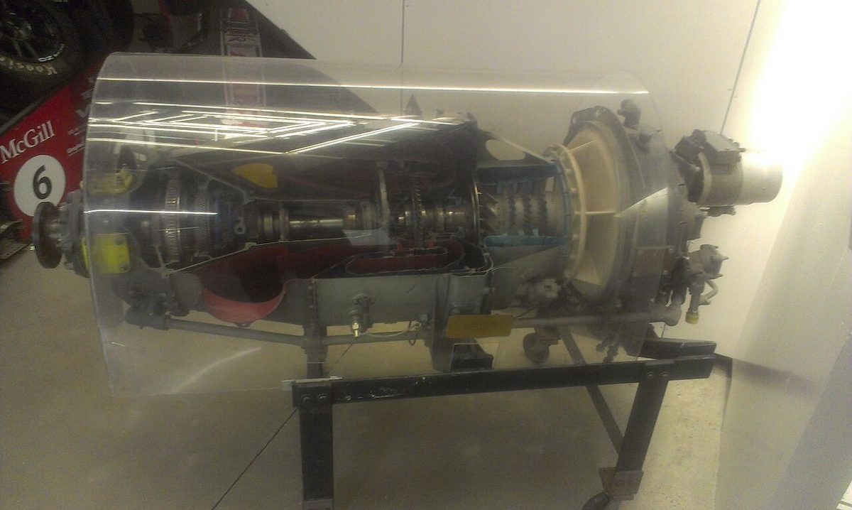
A turboprop's output is measured as shaft horsepower (SHP). The exhaust still gives a small residual jet thrust, and the total output, shaft power plus the horsepower equivalent of that thrust, is the equivalent shaft horsepower (ESHP). As altitude increases, both SHP and jet thrust fall with the mass of air through the engine. As airspeed increases at constant altitude, ram effect raises the mass flow and the SHP, while the net jet thrust decreases; fuel flow rises, but SHP rises faster, so the specific fuel consumption falls. A propeller converts power into thrust efficiently at moderate speeds, which suits the turboprop to shorter routes and lower cruise speeds.
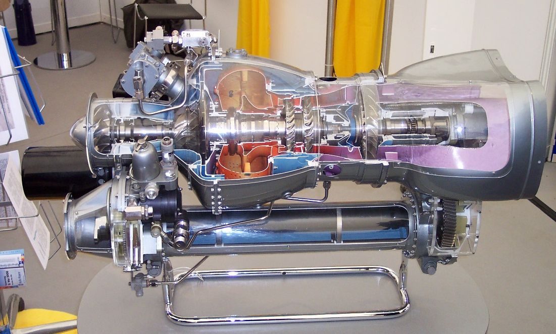
A turboshaft delivers all its useful power to an output shaft and produces practically no jet thrust. Helicopter engines are turboshafts, usually with a free power turbine driving the rotor gearbox. An auxiliary power unit is a small turboshaft: the A320's APU is a single-shaft gas turbine that drives an accessory gearbox for its generator and also supplies bleed air (see auxiliary power unit (APU)).
Single-, twin- and three-spool designs
A spool is a compressor and the turbine that drives it, joined by a shaft. In a single-spool engine the whole compressor turns at one speed. A twin-spool or two-spool engine has an LP spool, whose speed is N1, and an HP spool, whose speed is N2; the LP shaft runs inside the hollow HP shaft. A three-spool engine adds an intermediate spool; N1 remains the LP spool, N2 becomes the IP spool and N3 the HP spool.
| Engine | LP spool (N1) | HP spool (N2) |
|---|---|---|
| CFM56-5B (A320) | Single-stage fan, 4-stage LP compressor, 4-stage LP turbine | 9-stage HP compressor, single-stage HP turbine |
| IAE V2500-A5 (A320) | Fan and 4-stage LP compressor | 10-stage HP compressor |
| GE CF34-10E (E190) | 24-blade fan, 4-stage LP turbine | 9-stage HP compressor, single-stage HP turbine |
Splitting the compressor lets each spool turn at its own best speed. When the thrust is reduced the LP spool slows more quickly than the HP spool, which keeps the airflow over the blades at a suitable angle over a wider speed range and makes a multi-spool engine more resistant to stall. The starter only needs to turn the HP spool, and the external gearbox that drives the fuel and oil pumps and the generator is driven from it. Rolls-Royce builds three-spool engines, such as the Trent 900 of the A380, whose IP turbine drives the IP compressor.
Engines are often built by partners. International Aero Engines (IAE), maker of the V2500, was formed as a consortium of Pratt & Whitney, Rolls-Royce, MTU and Japanese Aero Engines Corporation; CFM International, maker of the CFM56 and LEAP, is a joint venture of GE and Safran.
Shaft horsepower and torque measurement
A shaft's power is the product of its torque and its rotational speed. Jet engines are set by N1 or engine pressure ratio (see engine indications and condition monitoring); propeller engines and turboshafts indicate torque, from which, at a known propeller speed, shaft horsepower follows.
A torquemeter measures it in one of two ways. In an oil torquemeter, helically cut gears in the propeller reduction gearbox produce an axial thrust proportional to torque; oil pressure in a set of cylinders balances that thrust, and the pressure needed is read as torque. An electronic torquemeter uses two concentric shafts, a torque shaft that carries the load and a reference shaft that does not. Toothed wheels on each pass a pick-up, and as the torque shaft twists under load the phase between the two signals changes in proportion to the torque. It can also show negative torque, as from a windmilling propeller.
Thrust augmentation
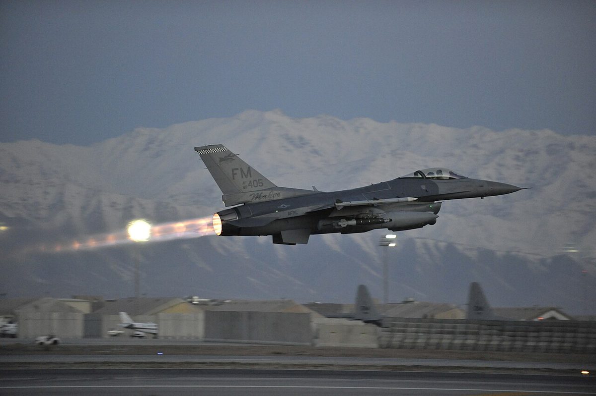
An afterburner, or reheat, burns extra fuel in the jet pipe behind the turbine. Much of the air passing through the engine has not taken part in combustion, so the turbine exhaust still contains enough oxygen to burn it. Reheat raises the exhaust gas temperature to as much as about 1,500 °C. Once a nozzle is choked, the gas cannot leave it faster than the local speed of sound, and only a higher gas temperature raises that speed, so reheat increases jet velocity and thrust. The penalty is a very high fuel consumption, which limits it to short periods; an afterburning engine also needs a propelling nozzle whose area can be increased when reheat is lit.
Water-methanol injection was used on older engines, including those of the Fokker F27, to restore take-off power on hot days and at high aerodromes. Injecting the mixture into the airflow cools the air, increasing its density and the mass flow through the engine; the methanol lowers the freezing point of the water and itself burns. Modern airliner engines do without it.
Nacelles and pylons
The engine nacelle is the streamlined housing around the engine. It includes the intake cowl, whose lip the engine anti-ice system heats with bleed air, the hinged fan cowls, the thrust reverser and the exhaust. It also contains the engine's fire zones: on the A320 the fire detection elements sit in the pylon nacelle area, the engine core and the fan section. A drain mast under the nacelle discharges fuel and oil that collect inside.
The engine pylon, also called the engine strut (the usual term in Boeing manuals), attaches the nacelle to the wing and carries the fuel, bleed air, hydraulic and electrical lines between them. Hanging the engines on pylons under and ahead of the wing has two structural benefits. Their mass relieves the upward bending of the wing in flight, and placed forward of the leading edge it acts as a mass balance that helps to prevent wing flutter (see flutter and aeroelasticity). A large fan also brings the nacelle close to the ground: the lowest point of the A320's is about 0.56 m above it.
Engines mounted on the rear fuselage have their thrust lines close to the centreline, so an engine failure gives much less yaw, and the wing is left clean. The penalties are the loss of wing bending relief, a centre of gravity further aft and a T-tail, which in a deep stall can sit in the wake of the wing and nacelles; such aircraft usually have a stick pusher.
Frequently asked questions
What is the difference between a turbojet and a turbofan?
In a turbojet all the air passes through the core and the thrust comes from a small mass of gas leaving at very high speed. In a turbofan a large fan, driven by the low-pressure turbine, sends most of its air round the core through a bypass duct. Moving a large mass of air at a lower speed is far more propulsively efficient at airliner speeds, and quieter, which is why turbofans have replaced turbojets on transport aircraft.
What is the bypass ratio of a jet engine?
Bypass ratio is the mass of air flowing through the bypass duct divided by the mass flowing through the core. A high-bypass turbofan has a ratio of roughly 5:1 to 12:1. On the A320 the CFM56-5B has about 5.9 and the IAE V2500 about 4.6, while new engines such as the LEAP and the geared turbofan reach about 11 to 12. On such engines the fan produces most of the take-off thrust.
What is a geared turbofan?
A geared turbofan places a reduction gearbox between the low-pressure shaft and the fan. The fan can then turn slowly enough for its large diameter, while the low-pressure compressor and turbine, linked directly to each other, run at the higher speed that suits them. The Pratt & Whitney PW1100G-JM of the A320neo and the PW1900G of the Embraer E2 are geared; the CFM LEAP-1A, the other A320neo engine, is not.
What is the difference between SHP and ESHP?
Shaft horsepower (SHP) is the power a turboprop delivers to its propeller shaft, found from the torque and the shaft speed. The exhaust of a turboprop still gives a small jet thrust, so its total output is expressed as equivalent shaft horsepower (ESHP): the shaft horsepower plus the horsepower equivalent of that residual thrust. Both fall as altitude increases, because the mass of air through the engine falls.
Why do jet engines have two or three spools?
A spool is a compressor and the turbine that drives it, joined by a shaft. Splitting the compressor between two or three spools lets each part turn at its own best speed, which widens the range of speeds over which the compressor works without stalling. It also means the starter only has to turn the high-pressure spool. N1 is the low-pressure spool; on a three-spool engine N2 is the intermediate and N3 the high-pressure spool.
Test yourself on Gas Turbine Engine Types
The v1prep banks cover this topic in Aircraft General Knowledge (021), with a worked explanation for every answer. EASA ATPL, PPL, IR and CPL, the FAA written tests and A320/B737 type ratings.
Start practising →Sources and further reading
- FAA Aviation Maintenance Technician Handbook, Powerplant (FAA-H-8083-32B), Chapter 1, Aircraft Engines
- EASA, Explanatory Note to ED Decision 2018/001/R, Part-FCL theoretical knowledge learning objectives (021 Powerplant)
- EASA Easy Access Rules for Engines (CS-E)
- 14 CFR Part 33, Airworthiness Standards, Aircraft Engines
- EASA Type-Certificate Data Sheet EASA.A.064, Airbus A318/A319/A320/A321 (engines)
- FAA Airplane Flying Handbook (FAA-H-8083-3C), Transition to Turbopropeller-Powered and Jet-Powered Airplanes
Library articles are written for study and exam preparation. They do not replace your aircraft's approved documentation, your operator's procedures or the regulations themselves.