B737 Flight Instruments and Displays
The Boeing 737 NG flight instruments are the primary flight, navigation and engine displays of the Common Display System, driven by two display electronics units from the air data inertial reference units and the navigation receivers, together with the standby instruments, the source transfer switches and the alerts that compare the two sides.
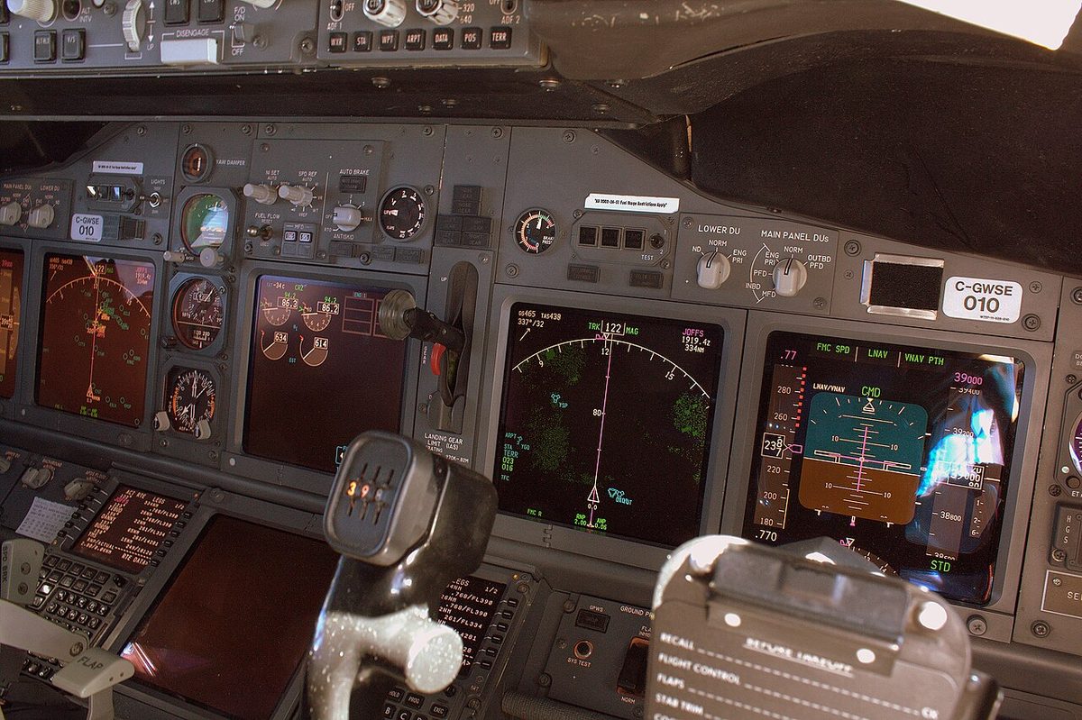
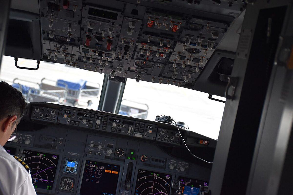
The Boeing 737 NG shows its flight, navigation and engine information on six display units managed by the Common Display System (CDS): an outboard primary flight display (PFD) and an inboard navigation display (ND) for each pilot, and an upper and a lower centre unit, the upper one normally showing the primary engine indications. Attitude, heading and air data come from two air data inertial reference units, and transfer switches on the overhead panel let one source serve both sides when a component fails.
This article follows the 737 NG flight crew operations manual (FCOM) and notes the differences of the 737 MAX, which shares the type rating. The general principles are in primary flight display, EFIS and IRS alignment and modes; the Airbus approach is in A320 EIS displays and EFIS controls.

Common Display System and DEUs
Two display electronics units (DEUs) generate the pictures. With the displays source selector at AUTO, DEU 1 drives the captain's outboard, captain's inboard and upper display units, and DEU 2 the first officer's outboard, first officer's inboard and lower units. If one DEU fails, the other takes over all six automatically; ALL ON 1 or ALL ON 2 does the same by hand. Whenever the displays run from a single DEU, an amber DSPLY SOURCE 1 or DSPLY SOURCE 2 annunciation shows on the PFDs.
A DEU failure reaches beyond the screens:
- Engines: loss of either DEU removes a signal from both EECs, whose ALTN lights come on as each reverts to alternate mode.
- Autoflight below FL220: in a climb or descent with the failed side's autopilot engaged, the flight director pitch bar disappears from both PFDs until ALT ACQ, the autopilot reverts to CWS P, and LVL CHG, VNAV and V/S are not available on that autopilot. Above FL220 the autopilot and flight directors are unaffected.
- Approach: a DEU failure before the second autopilot is engaged for a dual-channel approach inhibits that engagement.
On the ground before the second engine start, a white CDS MAINT reports a dispatchable CDS fault and an amber CDS FAULT a non-dispatchable one.
Display units and display switching
At preflight the MAIN PANEL DUs and LOWER DU selectors are set to NORM, the displays source selector to AUTO and the displays control panel switch to NORMAL. The selectors move pictures by hand: MAIN PANEL DUs at OUTBD PFD keeps the PFD on the outboard unit and blanks the inboard one, and at INBD ENG PRI puts the primary engine indications on the inboard unit with the PFD outboard. LOWER DU at ENG PRI moves the primary engine display to the lower unit and blanks the upper display unit.
Some failures switch automatically:
| Failure | Result |
|---|---|
| Outboard display unit | PFD moves to the inboard unit; outboard blanks |
| Upper display unit | Primary engine display moves to the lower unit; if the secondary display is already there, a compact engine display results |
| Lower display unit | No automatic switching |
On battery power alone the captain keeps the outboard PFD, the inboard ND, the clocks and the left EFIS control panel, and the upper unit shows N1, N2, fuel flow, EGT, fuel quantity and oil pressure, temperature and quantity.
On the 737 MAX, the MAX Display System's four large liquid crystal displays replace the six units, the display select panels, brightness, master dim and test are revised, and there is no compact engine display. The MAX has an integrated standby flight display (ISFD) as basic equipment, where the NG's basic fit is three standby instruments, with the ISFD on some aircraft. The ISFD takes attitude from its own inertial sensors, air data from the auxiliary pitot probe and alternate static ports, and magnetic heading from ADIRU No. 1. See standby instruments.
PFD speed tape and bugs
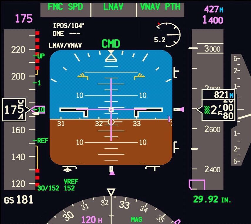
The white current airspeed shows calibrated airspeed above 45 kt, and Mach appears from M 0.40. The green speed trend vector points to the airspeed predicted 10 seconds ahead. The magenta selected speed is the MCP IAS/MACH value, or the FMC speed when that window is blank; off scale, its bug parks at the end of the tape as a half bug.
| Indication | Meaning |
|---|---|
| Red and black bar, top | Bottom of the bar is the lowest of Vmo/Mmo, gear placard and flap placard speeds |
| Amber bar, top (flaps up) | Maximum manoeuvre speed: 1.3 g to high-speed buffet, which corresponds to 40° of bank in level flight |
| Amber bar, top (after take-off) | Next flap position placard speed, which may show until 160 kt is exceeded or the first flap retraction |
| Amber bar, bottom | Minimum manoeuvre speed: 1.3 g to stick shaker below about 20,000 ft, to low-speed buffet above |
| Red and black bar, bottom | Stick shaker speed |
| Green numbered bugs | Flap manoeuvring speeds; removed at flaps 30 or 40, inhibited below VREF + 4; UP bug not shown above about 20,000 ft |
| White V2 + 15 | Removed at the first flap retraction or when VREF is entered |
The minimum manoeuvre speed bar appears with the first flap retraction after take-off or when a valid VREF is entered. Decelerating into it turns the airspeed box amber and flashing for 10 seconds and, where fitted, sounds "AIRSPEED LOW, AIRSPEED LOW" once. Anti-ice selection adjusts it and a wing asymmetry increases it (B737 warning systems). An amber SPD LIM flag means the stick shaker or maximum speed indication has failed and its bar is removed.
The speed reference selector (SPD REF) on the engine display control panel sets reference speeds by hand. In AUTO they come from the FMC. V1 and VR can be set only on the ground and VREF only in flight, the wrong phase giving INVALID ENTRY; SET removes the speed reference display. Bug 5 appears at BUG 5 or SET with a value above 60 kt. The amber NO VSPD flag stays on the PFD on the ground until V1 and VR are both entered on the CDU or set above 80 kt with the selector; it and TCAS OFF are the only flags expected at the preflight instrument check. V1 is removed at lift-off and called out by a voice aural.
PFD approach and landing symbology
The MINS selector on the EFIS control panel chooses BARO or RADIO minimums. The minimums reference turns amber and flashes for 3 seconds on descending below it, and returns to green at minimums plus 75 ft in a go-around, at touchdown or with the RST switch; the GPWS minimums callouts follow the captain's selector. The radio altitude readout appears below 2,500 ft, boxed white for 10 seconds as the aeroplane descends through 2,500 ft, and turns amber below the radio minimums.
On the ILS:
- The localiser pointer fills solid magenta within 2½ dots. The expanded localiser scale, on which a rectangle equals ½ dot, reverts to the standard scale out of LOC mode with groundspeed below 30 kt or radio altitude above 200 ft.
- Localiser deviation alerting self-tests when it arms at 1,500 ft radio altitude, with a two-second alert display on each attitude indicator. Below 1,000 ft, with LNAV engaged and LOC armed but not captured, the scale turns amber and the pointer flashes.
- The rising runway (green, magenta stem) shows below 2,500 ft radio altitude with a usable localiser and rises towards the aeroplane symbol below 200 ft.
- The glideslope pointer is removed when track and front course differ by more than 90°, as on a back course. Tuned ILS frequencies that disagree for more than a minute turn amber.
The Navigation Performance Scales (NPS) show deviation from the FMC path with actual navigation performance (ANP) bars. If the pointer stays within the ANP bars for 5 seconds, the bars turn amber and the pointer flashes for 10 seconds.
On the altitude tape a green crosshatch marks positive altitudes below 10,000 ft, and MTRS adds metric readouts of the current and selected altitudes. The barometric setting is boxed amber if a numeric setting is kept when climbing above the transition altitude, or STD when descending below the transition level.
ND and EFIS control panel
The EFIS mode selector chooses APP (localiser and glideslope, heading up), VOR, MAP (the FMC route, track up, with VNAV path deviation) or PLN (a fixed, true-north-up route picture stepped through on the CDU LEGS page). Weather radar, TCAS and terrain are not shown in PLN or centred APP. The CTR switch gives the full compass rose; in MAP, further pushes cycle through centre with the vertical situation display (VSD), expanded, and centre without VSD.
The EFIS map switches add data:
| Switch | Shows |
|---|---|
| WXR | Weather radar; returns limited to 320 NM on the 640 NM range |
| STA | All database navaids at 5 to 40 NM ranges, high-altitude navaids at 80 to 640 NM |
| WPT | Database waypoints off the route, at ranges of 40 NM or less |
| ARPT | Database airports in view |
| DATA | Altitude constraints, ETAs and the RNP of the next leg |
| POS | IRS and GPS positions and VOR bearing vectors |
| TERR | GPWS terrain; deselects the weather radar |
If an EFIS control panel fails in flight, its WXR selection goes OFF automatically. The VSD shows the vertical profile along the current track at half the selected range, with decision gates at 500 and 1,000 ft above field elevation. Its range to target speed dot (RTSD) marks where the aeroplane will reach the FMC or MCP target speed. The 737 MAX has a dedicated VSD switch on its EFIS control panel.
Instrument and navigation source transfer
The overhead NAVIGATION and DISPLAYS panels carry the transfer switches, all at NORMAL (or AUTO) at preflight:
- VHF NAV transfer switch: BOTH ON 1 makes the DEUs use multimode receiver 1 for both pilots' displays. The autopilot can use only VOR and ILS data that are displayed, so the VHF NAV source must match the engaged autopilot: CMD A uses VHF NAV 1, CMD B VHF NAV 2.
- IRS transfer switch: BOTH ON L makes the left IRS the attitude and heading source for both pilots' instruments. Whenever this switch is not at NORMAL, the amber INSTR SWITCH annunciation shows that both sides use the same IRU data.
- Displays source selector (above) and displays control panel switch: BOTH ON 1 sets both pilots' displays to the captain's EFIS control panel, BOTH ON 2 to the first officer's. An amber DISPLAYS CONTROL PANEL annunciation means a failed EFIS control panel on that side.
IRS and ISDU
The air data inertial reference system comprises two ADIRUs, each with an inertial and an air data section, four air data modules, one inertial system display unit (ISDU), one mode select unit, three pitot probes, six static ports, two alpha vanes and a TAT probe. Each IRS has three sets of laser gyros and accelerometers and is the only source of attitude and heading apart from the standby attitude indicator and compass. The captain's pitot feeds the left ADIRU and the first officer's the right, with no cross-connection.
A normal alignment, OFF to NAV, takes five to seventeen minutes depending on latitude and is possible only between 78°15'N and 78°15'S. A present position more than 4 NM from the origin airport gives VERIFY POSITION, and two consecutive entries failing the internal position test light FAULT. During transits, ALIGN while parked gives a 30-second fast realignment. If alignment is lost in flight, the navigation mode is lost for the rest of the flight; ATT relevels the IRS after about 30 seconds of straight, level, unaccelerated flight, but heading must be entered by hand and may drift by up to 15° per hour.
The left IRS is powered from the AC standby bus and the right from AC transfer bus 2. If AC fails they switch to DC from the switched hot battery bus, shown by the amber IRS ON DC light, and on the ground the nose wheel well horn sounds to warn of battery drain. The right IRS loses DC after 5 minutes without AC.
On the ISDU, TK/GS shows true track and groundspeed, and HDG/STS shows the minutes left in an alignment. Magnetic variation is stored only between 82°N and 82°S. The maximum flight operating latitude is 82°N or S, except, on most variants, 70°N between 80°W and 130°W and 60°S between 120°E and 160°E.
Disagree and comparator alerts
| Alert (amber, PFD) | Condition |
|---|---|
| IAS DISAGREE | Airspeeds differ by more than 5 kt for 5 seconds |
| ALT DISAGREE | Altitudes differ by more than 200 ft for more than 5 seconds |
| AOA DISAGREE | AOA values differ by more than 10° for more than 10 seconds; logic active above 400 ft radio altitude, and an alert showing on descent through 400 ft stays until landing |
| PITCH or ROLL (pitch/roll comparator) | Pitch or roll displays differ by more than 5°; flashes 10 seconds, then steady |
AOA DISAGREE, shown on both PFDs, does not say which value is wrong. On the 737 MAX, AOA DISAGREE first worked only with the optional AOA gauge; since the return to service it is standard on both PFDs. Its checklist now leads to the airspeed unreliable checklist, as IAS DISAGREE does (unreliable airspeed).
Frequently asked questions
What happens when a DEU fails on the Boeing 737 NG?
With the displays source selector in AUTO, the remaining display electronics unit automatically drives all six display units and an amber DSPLY SOURCE annunciation appears on the PFDs; each pilot still gets flight instrument data from independent sources. Both EECs revert to alternate mode. Below FL220 in a climb or descent with the failed side's autopilot engaged, the flight director pitch bars are removed and the autopilot reverts to CWS P.
What is the minimum manoeuvre speed amber bar on the 737 PFD?
The top of the amber bar on the lower speed tape is the minimum manoeuvre speed. Below about 20,000 ft it gives 1.3 g manoeuvre capability to the stick shaker, and above about 20,000 ft 1.3 g to low-speed buffet. It appears with the first flap retraction after take-off or once a valid VREF is entered, and an AIRSPEED LOW aural sounds where fitted when the speed decreases into it.
When does the AOA DISAGREE alert appear on the 737?
AOA DISAGREE appears in amber on both PFDs when the captain's and first officer's angle of attack values differ by more than 10 degrees for more than 10 seconds. It does not say which value is wrong. Its logic is active above 400 ft radio altitude, and an alert shown when descending through 400 ft remains until landing. On the 737 MAX it became standard on both PFDs with the display software update.
How long does a 737 IRS alignment take?
A normal alignment, started by turning the mode selector from OFF to NAV, takes between five and seventeen minutes depending on latitude, and can be done between 78 degrees 15 minutes north and south. A full alignment is recommended before each flight; during short transits a thirty-second fast realignment, selecting ALIGN while parked and updating the present position, removes the ground speed error.
What does the INSTR SWITCH annunciation mean on the 737?
The amber INSTR SWITCH annunciation shows that the captain's and first officer's displays are using the same source of IRU data. It appears when the IRS transfer switch on the overhead NAVIGATION panel is not at NORMAL, for example at BOTH ON L, which switches the attitude and heading source of both pilots' flight instruments to the left IRS.
Test yourself on B737 Flight Instruments and Displays
The v1prep banks cover this topic in the B737 type-rating bank, with a worked explanation for every answer. EASA ATPL, PPL, IR and CPL, the FAA written tests and A320/B737 type ratings.
Start practising →Sources and further reading
- FAA Flight Standardization Board Report, Boeing 737
- FAA, Summary of the FAA's Review of the Boeing 737 MAX (November 2020)
- EASA, Boeing 737 MAX Return to Service Report (January 2021)
- FAA Advisory Circular AC 25-11B, Electronic Flight Displays
- FAA Aeronautical Information Manual, Chapter 1 Section 1 (1-1-15, IRU, INS and AHRS)
- EASA Easy Access Rules for Large Aeroplanes (CS-25)
Library articles are written for study and exam preparation. They do not replace your aircraft's approved documentation, your operator's procedures or the regulations themselves.