Standby Instruments
Standby instruments are the independent flight instruments showing attitude, airspeed, altitude and heading that remain available when the primary displays, their sensors or the normal electrical supply fail. They have their own sensors and power so that no single failure removes all the information needed to fly.
Every modern flight deck is designed on the assumption that something will fail. Standby instruments are the last layer of that redundancy: a small set of flight instruments, showing attitude, airspeed, altitude and heading, that keep working when the primary displays, the computers behind them or the normal electrical supply have gone. They are deliberately simple, fed from their own sensors and powered from the battery, so that no single failure can leave the crew without what it needs to keep the aircraft upright, at a safe speed and at a known altitude.
In a light aeroplane the standby set may be no more than a battery-backed attitude indicator, the pitot-static instruments and the magnetic compass. In an airliner it is usually one integrated display in the centre of the panel, the Airbus integrated standby instrument system (ISIS) or the Boeing integrated standby flight display (ISFD), together with a standby magnetic compass. The principles, and most exam questions, are common to both.
Purpose of standby instruments
Primary flight instruments depend on a chain of units: probes and ports, air data computers, inertial or attitude and heading reference systems, display computers and screens, all powered by the aircraft's generators. Each link is duplicated, but duplication does not protect against a common cause, such as a total loss of generated power, a fault in the display system, or ice blocking several pitot probes in the same way. The standby instruments are a third, dissimilar source that shares as little as possible with the other two.
They serve three purposes:
- Continued flight. If both primary attitude sources or both air data computers fail, the crew flies on the standby instruments to a landing.
- Arbitration. When the captain's and first officer's indications disagree, the standby is the third opinion that helps identify the faulty side (see unreliable airspeed).
- Reference. The standby compass is the heading against which gyro and inertial heading can be checked.
The same logic applies to a light aeroplane with a glass cockpit. An air data computer failure removes airspeed, altitude and vertical speed from the primary flight display while attitude and heading remain; an attitude and heading reference system (AHRS) failure does the opposite. Knowing which unit feeds which indication tells the pilot which standby instrument takes over: the standby airspeed indicator and altimeter in the first case, the standby attitude indicator and the magnetic compass in the second (see attitude indicator). A red cross over an indication means the system has judged it invalid and removed it; it is not a caution to interpret. Some Boeing aircraft with EICAS extend the idea to the engines, with a standby engine indicator showing N1, N2 and EGT if the EICAS displays are lost.
Conventional standby instruments
Before integrated displays, and still on many aircraft, the standby set was three separate instruments: a standby attitude indicator, often called the standby horizon, a standby airspeed indicator and a standby altimeter, together with the standby compass. The Boeing 737 NG has the three instruments as basic equipment, with an ISFD fitted on some aircraft; on the 737 MAX the ISFD is basic.
Standby attitude indicator
The standby attitude indicator is a self-contained gyro horizon that works independently of the primary attitude displays. European operating rules for commercial air transport require it to provide reliable operation for at least 30 minutes after a total failure of the normal electrical generating system. On 737 variants with an electromechanical standby horizon, the instrument is powered from the battery bus and remains powered after the loss of all normal AC power for as long as battery power is available. Its gyro reaches operating speed about 60 seconds after power is applied and needs three minutes to meet its accuracy requirements. A GYRO flag shows that its attitude is unreliable.
The 737 instrument also carries localiser and glideslope pointers from the No. 1 ILS receiver. Its approach mode selector has three positions: OFF retracts the pointers, APP shows them, and B/CRS reverses the localiser sense for a back course approach and removes the glideslope pointer. Before flight the crew pulls and releases the caging control to set the display, selects the approach mode to OFF and checks that no flags are shown.
Standby airspeed indicator and altimeter
The standby airspeed indicator and standby altimeter are pneumatic instruments connected directly to a pitot probe and static ports that do not feed the main air data computers. On a typical CS-25 transport each main air data computer has its own pitot-static system and the standby instruments have a third, independent one. Because they need no computer, they remain available if both air data computers fail, and they are the only flight instruments on an air data flight deck that still need pneumatic lines behind the panel (see air data computer).
On the 737 NG the standby airspeed indicator takes ram pressure from the auxiliary pitot probe, on the first officer's side of the nose, and static pressure from the alternate static ports. The standby altimeter uses the same static ports, reads from -1,000 to 50,000 ft and shows its barometric setting in both hectopascals (millibars) and inches of mercury. The auxiliary pitot probe is not heated when the aircraft is on standby power, which matters in icing after a total generator loss.
Exam tip: standby altimeters do not meet RVSM accuracy requirements. RVSM depends on the primary air data systems, so after the loss of both primary altimetry systems the crew must expect to leave RVSM airspace.
Integrated standby systems (ISIS and ISFD)
An integrated standby system replaces the three separate instruments with one small display. It computes attitude from its own inertial sensors and airspeed and altitude from its own pressure sensors, connected directly to the standby pitot and static sources. Airbus calls it the integrated standby instrument system (ISIS); Boeing calls the 737 unit the integrated standby flight display (ISFD). On the Embraer E190-E2 the standby unit has its own air data computer and inertial reference and, like the others, is not approved for RVSM use.
On the A320 the ISIS shows attitude, airspeed, Mach number, altitude and the barometric setting, and can add ILS deviation scales and reference bugs; it does not show wind. The pitch scale is marked every 2.5° between 30° nose-up and 30° nose-down, with red chevrons beyond pointing the way back, and the bank scale at 0°, 10°, 20°, 30°, 45° and 60°. Mach number appears above M 0.5, and pressing the BARO knob selects standard pressure. The ISIS and ADR 3 take pitot pressure from the same standby probe, so agreement between those two sources does not prove that either is right.
Three ISIS functions carry cautions:
- Attitude reset. Pressing ATT RST for at least 2 seconds with the aircraft level realigns the attitude in about 10 seconds. A reset is required after 350 hours of continuous power, and an ATT: RST flag calls for one after excessive movement during alignment.
- LS function. It must not be used for a take-off using the localiser of the opposite runway, or for a back course approach, because the localiser deviation would be shown in the wrong sense.
- Bugs. Airbus recommends against using them: if both primary flight displays were lost in flight, bugs set for take-off would still be showing during the approach.
On the 737 ISFD, attitude comes from internal inertial sensors, airspeed and altitude from the auxiliary pitot probe and alternate static ports, localiser and glideslope deviation from the No. 1 multi-mode receiver, and magnetic heading from the No. 1 ADIRU. It is powered from the battery bus: about 10 seconds after the battery switch is selected on, a 90-second initialisation begins, with ATT and INIT 90s shown. After a momentary out-of-limit condition an ATT:RST message appears, and the reset must be made on the ground with the aircraft stationary, or in flight in wings-level, unaccelerated flight. Magnetic heading is not available in polar regions, although later versions switch automatically to true heading, and the standby compass is used to validate the ISFD heading. The E190-E2 unit likewise has a 90-second alignment during which the aircraft must not be moved.
Standby magnetic compass
The standby magnetic compass, or standby compass, is a conventional liquid-damped, direct-reading magnetic compass with a correction card for the installation nearby. It needs no electrical power, vacuum or alignment, which is why it survives on the most automated flight decks. On the A320 it sits on top of the windscreen centre post with its deviation card above it. The card may give separate corrections with the radios on and off.
The compass has integral lighting. On the A320 the ICE IND & STBY COMPASS switch controls both its light and the external ice detector light. On the 737, standby power keeps the standby compass light on, together with the dome and instrument flood lights, when normal electrical power is lost.
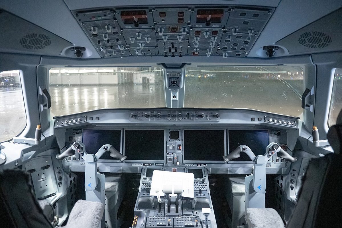
Its limitations are those of every direct-reading compass (see magnetic compass). The magnet system is pendulous, so it shows turning errors through north and south and acceleration errors on east and west headings, and it reads correctly only in straight, level, unaccelerated flight once the card has settled. Its main role is as a reference: to check inertial or gyro-magnetic heading, to reset a remote compass that has been switched to free (DG) mode after a magnetic sensing failure or at high latitude, and to validate the heading on a standby display (see heading indicators and compass systems).
Power supply and independence
A standby instrument is only useful if it does not fail with the primary instruments, and designers keep it independent in three ways:
- Separate sensors. Standby airspeed and altitude come from their own pitot and static sources, and standby attitude from a separate gyro or inertial unit.
- Separate power. Standby instruments run from the battery or from buses that remain powered after the generators fail. On the 737 both the electromechanical standby horizon and the ISFD are on the battery bus.
- Separate processing. Integrated standby units compute their own attitude and air data rather than taking them from the main computers.
Independence has limits worth knowing. A shared probe links the A320's standby instruments to ADR 3. In degraded electrical configurations the standby pitot heating can be lost: on the 737 the auxiliary pitot is not heated on standby power, and on the A320 the standby probes lose their heating in the emergency electrical configuration, except that the standby pitot is moved to the AC essential bus if the captain's air data has been switched to ADR 3. Battery endurance is finite, so a total generator loss starts a clock for the landing.
In light aeroplanes, traditional panels split the power sources: vacuum-driven attitude and heading indicators and an electric turn coordinator, so that either failure leaves one working gyro instrument. Glass cockpits recreate the principle with an electric standby attitude indicator or integrated unit with its own battery. Its battery test and a check that the instrument erects are part of the pre-flight checklist, because in a total electrical failure the standby attitude indicator, the magnetic compass and the pitot-static instruments may be all that remain.
Using the standby instruments
Standby instruments are part of the normal scan, not only of emergencies. The crew sets them like the primaries: at the transition altitude an A320 crew sets STD on both EFIS control panels and on the standby altimeter, and QNH on all three at the transition level. They are included in routine cross-checks of speed and altitude, so a divergence is noticed early.
When the primary indications disagree, the standby becomes the tie-breaker, with care. On the 737 NG the amber IAS DISAGREE alert appears when the captain's and first officer's airspeeds differ by more than 5 kt for 5 seconds. Comparing both with the standby, and all three with pitch, thrust and ground speed, identifies the faulty source; majority voting alone can mislead when a common cause affects two sources. The A320's backup speed scale (BUSS), shown on both PFDs once all three ADRs are switched off, replaces the normal speed scale and puts GPS altitude in place of barometric altitude; it is a different kind of backup from the standby instruments.
Flying on the standby instruments is hard work. The display is small, often placed in the centre panel away from the pilot's normal line of sight, and under the stress of a failure attention narrows, so flags and standby instruments are easily overlooked. The crew hands over tasks so that the pilot flying can concentrate on attitude, keeps manoeuvres gentle and plans an early landing, particularly when the standby instruments are running on battery power.
Frequently asked questions
What is the difference between ISIS and ISFD?
They are two names for the same idea. ISIS, the integrated standby instrument system, is the Airbus term; ISFD, the integrated standby flight display, is Boeing's. Each replaces the separate standby horizon, airspeed indicator and altimeter with one small display that computes attitude from its own inertial sensors and airspeed and altitude from its own pressure sensors, connected to the standby pitot and static sources. The 737 ISFD is powered from the battery bus.
How long must a standby attitude indicator work after an electrical failure?
European operating rules for commercial air transport require the standby attitude indicator to provide reliable operation for at least 30 minutes after a total failure of the normal electrical generating system. It is therefore powered from the battery or a standby bus. On 737 variants with an electromechanical standby horizon it is on the battery bus and stays powered after the loss of all normal AC power as long as battery power lasts.
Can the standby altimeter be used in RVSM airspace?
No. The standby altimeters of transport aircraft do not meet the accuracy requirements of RVSM airspace, which rely on the primary air data systems. The Boeing 737 limitations say so directly, and Embraer's E190-E2 standby unit is likewise not for RVSM use. If both primary altimetry systems fail, the crew must expect to leave RVSM airspace and fly at non-RVSM levels.
Where do the standby airspeed and altitude come from?
From a pitot probe and static ports that do not feed the main air data computers, usually a third, independent pitot-static system. On the 737 NG the standby airspeed takes ram pressure from the auxiliary pitot probe on the first officer's side and static pressure from the alternate static ports. On the A320 the standby instruments share the standby pitot probe with ADR 3, so their agreement is not independent proof.
What is the standby compass used for?
The standby compass is a liquid-damped, direct-reading magnetic compass that needs no power. It is the heading reference of last resort and the check on other heading sources: the crew uses it to verify inertial or gyro heading, to reset a remote compass in free mode and to validate a standby display's heading. It is accurate only in straight, level, unaccelerated flight, after the card has settled.
Test yourself on Standby Instruments
The v1prep banks cover this topic in Instrumentation (022), with a worked explanation for every answer. EASA ATPL, PPL, IR and CPL, the FAA written tests and A320/B737 type ratings.
Start practising →Sources and further reading
- EASA Easy Access Rules for Air Operations (Regulation (EU) No 965/2012), instruments and equipment (NCO.IDE, CAT.IDE)
- EASA Easy Access Rules for Large Aeroplanes (CS-25), CS 25.1327 Magnetic direction indicator
- 14 CFR 25.1327, Magnetic direction indicator
- FAA Instrument Flying Handbook (FAA-H-8083-15B), Chapter 5, Flight Instruments
- FAA Pilot's Handbook of Aeronautical Knowledge (FAA-H-8083-25), Chapter 8, Flight Instruments
- FAA Flight Standardization Board Report, Boeing 737, Revision 17
- 14 CFR 91.205, Powered civil aircraft with standard U.S. airworthiness certificates, instrument and equipment requirements
Library articles are written for study and exam preparation. They do not replace your aircraft's approved documentation, your operator's procedures or the regulations themselves.