Inertial Navigation System (INS)
An inertial navigation system (INS) is a self-contained navigation system that computes position, velocity, attitude and heading from gyros and accelerometers, by integrating measured accelerations twice from a known starting position. It needs no external signal once aligned, but its position error grows with time.
An inertial navigation system (INS) works out where the aeroplane is without receiving anything from outside. Gyros and accelerometers sense every rotation and acceleration, and a computer integrates them from a known starting point into velocity and position. It needs no ground station or satellite, so it keeps working where radio aids and GNSS are unavailable, and it gives attitude and heading as well as position, which made it a standard long-range navigation system for airliners and keeps it the backbone of their flight displays.
The terms overlap. The FAA's AIM calls the sensor unit of gyros and accelerometers an inertial reference unit (IRU), which gives attitude, heading, position and velocity, and describes an INS as an IRU combined with a navigation computer that flies a programmed series of waypoints. Modern airliners carry strapdown inertial reference systems (IRS), often combined with air data in an ADIRU, and leave the navigating to the flight management system; their alignment and modes are covered in inertial reference system alignment and modes.
Inertial navigation principle
Inertial navigation is dead reckoning by measurement. Newton's laws say that any change in the aeroplane's velocity requires an acceleration. Measure every acceleration, in known directions and from a known starting velocity and position, and the path can be reconstructed.
Two kinds of sensor are needed. Accelerometers measure acceleration along their axes. Gyros establish the directions of those axes relative to the Earth: level, and aligned with true north. A computer combines the two, removes the effects of gravity and the Earth's rotation, and integrates. The starting position is entered during the ground alignment; after that the system is self-contained.
Accelerometers and double integration
The classic linear accelerometer (LA) is a small pendulous mass. When the aeroplane accelerates, inertia swings the pendulum off its null position; a pick-off detects the movement and a torque motor drives it back. The current needed to hold the pendulum at null is proportional to the acceleration, and it is the output.
That output is integrated twice. The first integration turns acceleration into velocity; the second turns velocity into distance. A north-south and an east-west accelerometer give distance north and distance east. Distance north converts directly into change of latitude, one minute of latitude per nautical mile. Distance east, the departure, must be multiplied by the secant of the latitude to give change of longitude, because the meridians converge.
The integration is unforgiving. Left to itself, any constant error in an accelerometer's output, its accelerometer bias, would be integrated into a velocity error growing with time and a position error growing faster still; Schuler tuning, described below, is what contains it. Gravity is the biggest trap: an accelerometer tilted even slightly from the horizontal senses a component of gravity and reports it as a horizontal acceleration. Keeping the horizontal accelerometers truly level, or knowing exactly how far they are tilted, is the central problem of inertial navigation.
Gimballed and strapdown platforms
The first airline systems solved it mechanically. A gimballed inertial platform carries the accelerometers and three gyros on a stable element mounted in gimbals. The gyros sense any rotation of the platform, and their signals drive gimbal torque motors that hold it level and aligned with north whatever the aeroplane's attitude.
A platform held fixed in space would not stay level, because the Earth turns and the aeroplane moves over its curved surface. The computer therefore torques the gyros continuously:
- for Earth rate, 15.04° per hour (the sidereal rate), with a vertical component of 15.04° × sine of latitude, which would make the platform drift in azimuth, and a horizontal component of 15.04° × cosine of latitude, which would tilt it;
- for transport rate, the aeroplane's velocity divided by the Earth's radius, which keeps the platform level as it travels;
- for Coriolis and centrifugal effects and for the oblate shape of the Earth.
A strapdown inertial system drops the gimbals. Three gyros and three accelerometers are fixed to the airframe, and a computer keeps a mathematical platform: from the gyro rates it calculates at every instant the transformation from aircraft axes to Earth axes, and resolves the accelerations into north, east and vertical. With no gimbals, bearings or torque motors the system is lighter and far more reliable, and it is insensitive to manoeuvres.
| Gimballed INS | Strapdown IRS | |
|---|---|---|
| Sensors | On a stabilised platform | Fixed to the airframe |
| Levelling and alignment | Torque motors hold the platform | Computed mathematically |
| Typical gyros | Spinning-rotor gyros | Ring laser or fibre optic gyros |
| Ground alignment | About 20 to 30 minutes | About 5 to 10 minutes |
| Gimbals and spinning rotors | Yes | No |
Real, random gyro drift cannot be compensated by calculation; it remains the main error source in both designs.
Ring laser gyro and Sagnac effect
The ring laser gyro (RLG) is the gyro of nearly all modern airliner inertial systems. It has no spinning rotor. A triangular block of temperature-stable glass has tunnels drilled round its perimeter, with a mirror at each corner, and is filled with a helium-neon gas mixture that lases when a high voltage is applied. Two laser beams travel round the closed path in opposite directions.
Lasing requires the path length to be a whole number of wavelengths. When the block rotates about its axis, the beam travelling with the rotation has slightly further to go and the one travelling against it slightly less, the Sagnac effect. Their wavelengths, and so their frequencies, shift apart by an amount proportional to the rate of rotation. One mirror lets a little light through, a prism combines the beams, and a photoelectric cell reads the moving interference fringes: the direction of movement gives the direction of rotation, the speed of movement the rate.
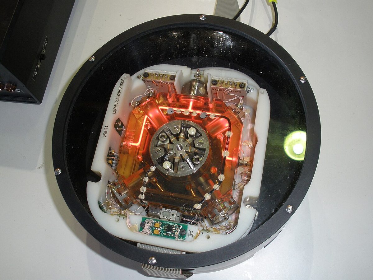
With no bearings or rotor imbalance, an RLG's drift comes mainly from noise caused by imperfections in the mirrors and their coatings. Its accuracy increases with the length of the optical path, which is limited by the size of the package. The fibre optic gyro (FOG) extends the idea with a long coil of optical fibre in place of the laser cavity, giving a long path in a small unit; exam texts note the Airbus A380 as the first commercial transport with fibre optic gyros in its IRS.
Laser lock-in and dither
The RLG has one weakness. At very low rotation rates, light scattered back from imperfections in the mirrors couples the two beams, and their tiny frequency difference disappears as they lock together. This laser lock-in leaves the gyro blind to slow rotations, the very rates a navigation sensor must measure.
The cure is dither. A piezo-electric dither motor vibrates the laser block through small angles at high frequency about its input axis, so that it passes through the lock-in region too quickly for locking to develop. The dither motion is filtered out of the output. Fibre optic gyros do not suffer from lock-in and need no dither.
Schuler tuning
A tilted platform senses part of gravity as acceleration and turns it into false velocity and position. What keeps such errors in check is Schuler tuning. Schuler imagined a pendulum as long as the Earth's radius, its bob at the centre of the Earth: however its suspension point is accelerated along the surface, the bob stays vertically below it. Its period, 2π√(R/g), is 84.4 minutes. By feeding back velocity divided by the Earth's radius, an inertial system is made to behave like that pendulum, and it stays on the local vertical as it moves over the curved Earth.
A displaced Schuler-tuned system oscillates with an 84.4-minute period instead of diverging, which divides its errors into two kinds:
- Bounded errors oscillate and return to zero within each Schuler cycle. They come from an initial tilt of the platform, inaccurate acceleration measurement and first-stage integration errors.
- Unbounded errors keep growing. They come from an initial azimuth misalignment, drift of the azimuth gyro, drift of the levelling gyros and second-stage integration errors.

Because the unbounded errors grow with time, inertial accuracy is quoted as a rate: exam texts give figures of 1 to 2 NM per hour for an airliner system, the radial error rate. Attitude and heading remain reliable while the position drifts.
Baro-inertial vertical channel
Height is harder. Vertical position comes from integrating vertical acceleration twice, after the computer has subtracted gravity, about 9.81 m/s². The Schuler loop does not act in the vertical, and a tiny error in the gravity figure or an accelerometer bias is integrated into a height error that diverges quickly: a pure inertial vertical channel is unstable.
The IRS therefore takes barometric altitude from the air data computer and uses it to hold the vertical channel in a feedback loop, the baro-inertial vertical channel. The combined output is more accurate than either the inertial or the barometric figure alone. The air data computer also supplies true airspeed, from which the IRS computes the wind as the difference between its ground velocity and the air velocity.
Kalman filter and GPIRS hybrid
Inertial and radio positions have opposite qualities. The inertial position is smooth and accurate over minutes but drifts over hours; GNSS and DME/DME positions do not drift but jump about from fix to fix. A Kalman filter combines them, weighting each source by its expected error, so that the blended position has the short-term smoothness of the inertial solution and the long-term accuracy of the radio or satellite fix. Flight management systems use such filters to mix the positions of all their inertial units with GNSS, DME/DME and VOR/DME updates (see FMS navigation and position updating).
On the A320 the GPS data go to the ADIRUs, and each computes a GPIRS hybrid position, a GP-IRS position that the flight management and guidance computers use. With GPS bounding the drift, the error rate of an FMS position can fall below 0.05 NM per hour. The inertial side also supports GNSS integrity monitoring (see GNSS integrity and RAIM) and keeps the navigation going through a GNSS outage.
Redundancy matters as much as accuracy. With three inertial systems a failing one is found by comparing all three, a voting system; with two, a disagreement shows only that one is wrong, and a malfunction code or an external fix is needed to tell which. In oceanic airspace an INS or IRS counts as one of the two independent long-range navigation systems required, and an IRS-only aircraft on an RNP 10 route is typically limited to about 6.2 hours after its last position update (see oceanic and North Atlantic operations).
Exam tip: the Schuler period is 84.4 minutes; errors from tilt and accelerometer errors are bounded by it, while gyro drift and azimuth misalignment produce unbounded errors, which is why inertial accuracy is stated in NM per hour.
Frequently asked questions
How does an inertial navigation system work out position?
Accelerometers measure the aeroplane's accelerations along known axes, held level and referenced to north by gyros, or computed that way in a strapdown system. Integrating acceleration once gives velocity; integrating again gives distance travelled north-south and east-west. Added to the starting position entered at alignment, this gives present latitude and longitude continuously, with no external signal. Errors in the measurements accumulate, so the position slowly drifts.
What is Schuler tuning?
Schuler tuning makes an inertial system behave like a pendulum as long as the Earth's radius, whose period is 84.4 minutes. A platform, or its mathematical equivalent, tuned this way stays on the local vertical as the aeroplane moves over the curved Earth. Errors from an initial tilt or an accelerometer error then oscillate with an 84.4-minute period instead of growing without limit; those from gyro drift still grow with time.
What is the difference between an INS and an IRS?
In the classic INS the gyros and accelerometers sit on a gimballed platform kept level and aligned with north by torque motors, and a built-in computer navigates between waypoints. An IRS is strapdown: ring laser gyros and accelerometers are fixed to the airframe and a computer does the platform's job mathematically. The IRS supplies position, attitude and heading, and the flight management system does the navigating.
What is laser lock-in and how is it prevented?
At very low rotation rates the two counter-rotating beams in a ring laser gyro are coupled by light scattered back from imperfections in the mirrors, and their frequencies lock together, so slow rotation goes undetected. A piezo-electric dither motor prevents this by vibrating the laser block about its axis, carrying it through the lock-in region too fast for locking to occur. The dither motion is removed from the output signal.
How accurate is an inertial navigation system?
Unaided, an airliner inertial system drifts by a figure usually quoted as 1 to 2 NM per hour, and the error keeps growing with time in navigation mode. Attitude and heading stay accurate. Blended by a Kalman filter with GPS, which bounds the drift, the resulting position error rate can be below 0.05 NM per hour, while the inertial system smooths the solution and carries on if GPS is lost.
Test yourself on Inertial Navigation System (INS)
The v1prep banks cover this topic in Instrumentation (022), with a worked explanation for every answer. EASA ATPL, PPL, IR and CPL, the FAA written tests and A320/B737 type ratings.
Start practising →Sources and further reading
- FAA Aeronautical Information Manual, Chapter 1 Section 1 (1-1-15, IRU, INS and AHRS)
- FAA Aeronautical Information Manual, Chapter 1 Section 2 (RNAV sensors, DME/DME/IRU and hybrid GPS/inertial systems)
- FAA Instrument Flying Handbook (FAA-H-8083-15B), Chapter 9, Navigation Systems
- ICAO NAT Doc 007, North Atlantic Operations and Airspace Manual (2026 edition)
- EASA, Explanatory Note to ED Decision 2018/001/R, Part-FCL theoretical knowledge learning objectives (022 Instrumentation, 061 General Navigation)
Library articles are written for study and exam preparation. They do not replace your aircraft's approved documentation, your operator's procedures or the regulations themselves.