Angle of Attack, Stall Warning and Stall Protection
Angle of attack (AoA) sensing measures the angle between the relative airflow and a reference line of the aircraft, using vanes or pressure probes. Stall warning and stall protection systems use that angle, corrected for configuration, to warn the crew before the stall and, on some types, to push the nose down or limit the angle automatically.
A wing stalls when it exceeds its critical angle of attack, whatever the speed, weight or attitude. A warning that looked only at airspeed would have to allow for weight, bank angle, load factor and flap setting, and it would still be wrong in a pull-up or a gust. Measuring the angle of attack directly avoids those errors, so almost every stall warning, from the horn of a light trainer to the stick shaker of an airliner, is built on an angle of attack sensor.
The same measurement feeds more than the warning. It drives the minimum speed bands on the speed tape, the pitch limit indicator, the stick pusher of some types and the high angle of attack protection of fly-by-wire aeroplanes. Because so much depends on a few small sensors, their failure modes are part of the subject, as recent accidents have shown. The aerodynamics of the stall itself are covered in stall.
Angle of attack sensing
The angle of attack is the angle between the wing chord and the relative airflow. A sensor cannot sit on the chord line, so it measures the direction of the local airflow where it is mounted, usually on the side of the forward fuselage or on the wing. The flow there is bent by the fuselage and by the wing's own upwash, and the bending changes with flap and slat position. The computers that use the signal therefore apply a calibration for the sensor's position and modify the signal when flaps or slats extend.
The advantage is independence from weight and load factor. On the Boeing 737 the autoflight system's minimum speed, about 1.3 VS for the current flap setting, is computed from the angle of attack vanes for this reason: it keeps a margin from the stall at any weight, attitude and load factor.

AoA vanes and probes
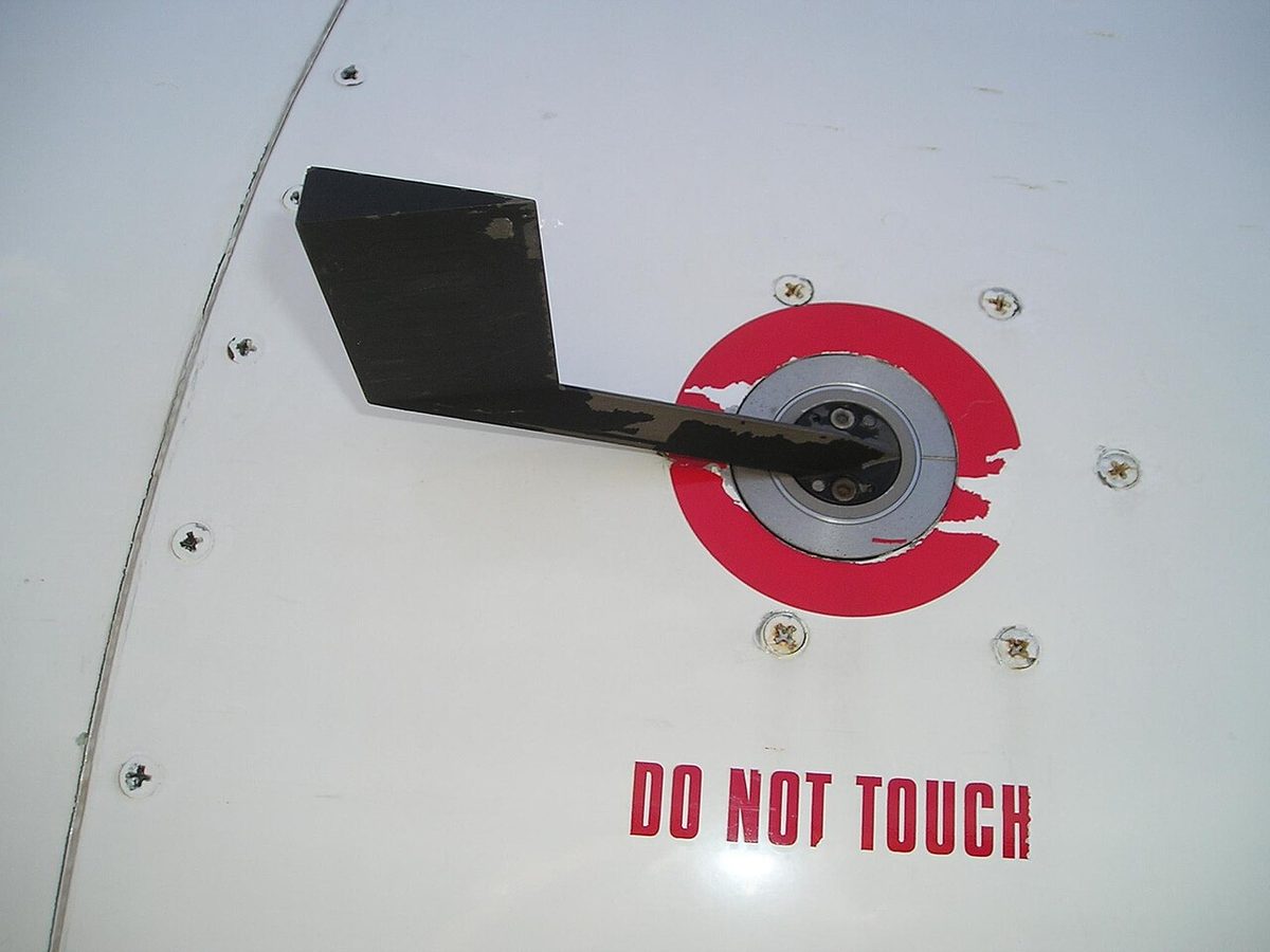
The angle of attack vane, or alpha vane, is a small fin on a shaft that is free to rotate. Like a weathervane it lines up with the local airflow, and a transmitter inside the fuselage, typically a synchro or resolver, sends the shaft angle to the computers (see sensors and transducers). The Boeing 737 has two alpha vanes, one on each side of the forward fuselage; the A320 has three angle of attack sensors, for the captain, the first officer and the standby side.
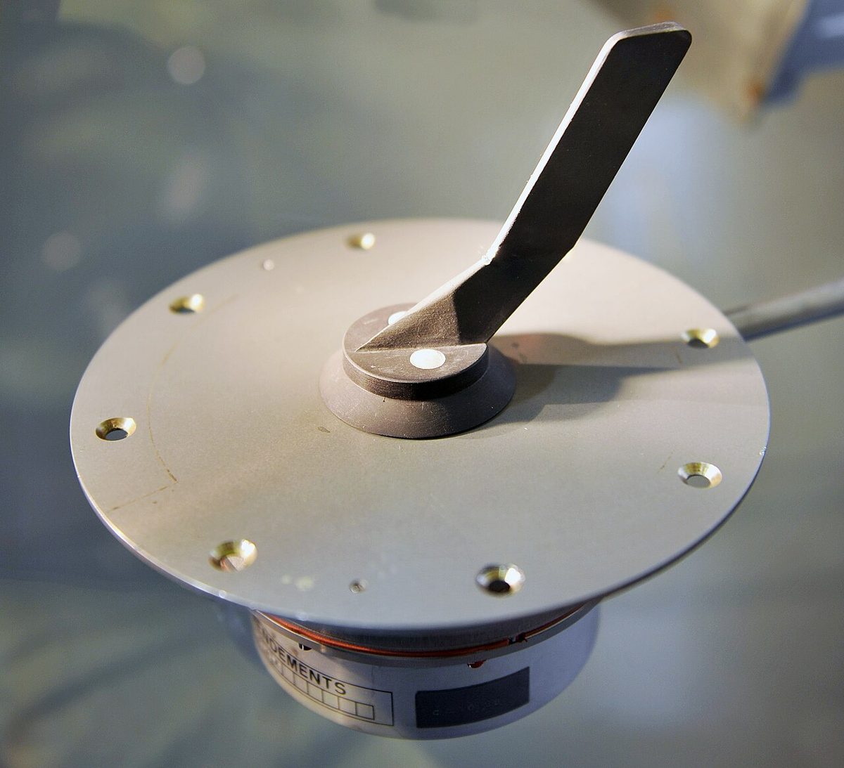
Other designs measure pressure rather than direction. An angle of attack probe carries two slots on its forward face; the pressure difference between them changes with the angle, and a null-seeking probe rotates until the two pressures balance, its rotation then giving the angle.
Light aeroplanes usually have no angle of attack sensor as such. Their stall warning comes from a small vane or a reed in the wing leading edge. As the angle of attack increases, the stagnation point moves aft along the underside of the leading edge and air begins to flow upward round it. The vane is lifted to close a switch for a horn or light, or the suction sounds the reed.
Vanes and probes stand in the airflow like pitot probes and are electrically heated. Ice on a vane changes the angle it reports, and a vane damaged on the ground, by a bird or by careless handling reports a false angle from the start of the flight.
AoA indicators and the pitch limit indicator
An angle of attack indicator shows the angle itself, usually on a scale or coloured bands that read the same at any weight. On airliners the gauge is less common: on the Boeing 737 it is an option on the primary flight display, while the angle is used everywhere behind the scenes.
The pitch limit indicator (PLI) is one such use. On the Boeing 737 it is an amber symbol on the attitude display that shows the pitch attitude at which the stick shaker would activate in the existing flight conditions. It is shown whenever the flaps are not up, and at slow speeds with the flaps up. Keeping the aircraft symbol below it preserves a margin from the stall warning, which is what a pilot needs in a windshear or terrain escape. The A320 has a different pitch limit on its PFD: a tailstrike limit, which appears at 400 ft radio height on approach and shows the maximum pitch attitude for landing with the main gear compressed.
The low speed markings of the speed tape are the most familiar display. On the 737 the stick shaker bar and the minimum manoeuvre speed band come from the same stall warning computation and move when its logic changes, as it does for icing. On the A320 a red and black VSW strip shows the stall warning speed when normal law is lost.
Stall warning systems
A transport aeroplane's stall warning system compares the measured angle of attack with a threshold that depends on configuration. Typical inputs are angle of attack, flap and slat positions, air/ground state and airspeed; on the 737 the two stall management yaw damper (SMYD) computers also take ADIRU data, the anti-ice selections and thrust. Engine fuel flow is not an input. Outputs are the stick shaker, an aural warning or synthetic voice and, on many types, the master warning light.
- Air/ground logic. The weight-on-wheels signal disables the warning on the ground, where it would otherwise sound continuously, and arms it in flight. The 737 system is armed in flight at all times.
- Icing. A contaminated wing stalls at a lower angle of attack, so the warning for a clean wing may come too late. On the 737, selecting engine anti-ice on sets the stick shaker logic for icing conditions and moves the minimum manoeuvre speed bars.
- Aural warnings. The A320 uses a cricket sound with a synthetic "STALL" voice and a red STALL message on the PFD, active in the degraded laws.
- Priority. Stall warning takes priority over windshear, GPWS and ACAS alerts: a crew with a stall warning and an ACAS resolution advisory at the same time respects the stall warning first.
Stall warning requirements
For large aeroplanes CS 25.207 and 14 CFR 25.207, which are harmonised, require a clear and distinctive warning with enough margin to prevent an inadvertent stall. The warning may come from the aeroplane's natural buffet or from a device giving clearly distinguishable indications, and a visual device that needs the crew's attention inside the flight deck is not acceptable on its own.
| Item | CS-25 / Part 25 requirement |
|---|---|
| Warning margin | At least 5 kt or 5 % CAS, whichever is greater, above the stall identification speed |
| Test condition | Speed reduced at no more than 1 kt per second |
| Duration | Until the angle of attack is reduced to about that at which the warning began |
| With a stick pusher | VSR at least 2 kt or 2 %, whichever is greater, above the pusher speed |
The stall identification point is defined in CS 25.201 as a nose-down pitch that cannot readily be arrested, buffeting strong enough to deter further speed reduction, or the pitch control reaching its aft stop with no further increase in pitch attitude. Where a stick pusher is fitted, its activation is accepted as the stall identification. For light aeroplanes FAA handbooks describe stall warners that typically sound about 5 to 10 kt above the stall in any flap configuration.
Exam tip: the regulatory stall warning margin is 5 kt or 5 % CAS, whichever is the greater. The stick pusher margin, used to set VSR, is 2 kt or 2 %, whichever is the greater.
Stick shaker
The stick shaker is a tactile warning that vibrates the control column. On the Boeing 737 it consists of two eccentric weight motors, one on each column, driven by the two independent SMYD computers; the vibration can be felt on both columns. It is a warning only: it applies no nose-down force. On the 737 NG the autopilot disengages if the stick shaker activates and persists for more than 5 seconds.
The response is to reduce the angle of attack, not to hold altitude. On Colgan Air flight 3407 in 2009 the captain answered the stick shaker by pulling back, and the Q400 stalled and crashed near Buffalo. Because the shaker is driven by angle of attack, not by pitot or static pressure, a shaker in an airspeed disagreement is taken seriously unless the angle of attack sensors themselves are suspect (see unreliable airspeed).
Stick pusher
A stick pusher acts rather than warns. At a set angle of attack it applies a strong nose-down force to the control column, quoted in ATPL texts at about 80 lbf, and releases it once the angle of attack has fallen. It is fitted where the natural stall is unacceptable, typically on T-tail aeroplanes whose stalled wing wake can blanket the elevator and lead to a deep stall that develops too fast for a pilot to stop.
A pilot can overpower a pusher. The NTSB found that the Colgan captain did so, holding the aeroplane stalled. Not every type uses one. The Embraer E190 (first generation) has no stick pusher; its flight control system reduces nose-up column authority progressively once the stick shaker has activated. The Boeing 737 has none either, but the 737 NG's elevator feel shift module roughly doubles column force near the stall, and on the 737 MAX the Maneuvering Characteristics Augmentation System (MCAS) adds nose-down trim at high angle of attack to restore the required pull force.
Envelope protection
Fly-by-wire aeroplanes can go further and prevent the stall. In the Airbus A320's normal law the high angle of attack protection takes over when the angle of attack exceeds alpha prot: the sidestick then commands angle of attack instead of load factor. Even with the stick held fully back the angle does not exceed alpha max, just below the 1 g stall, and if the stick is released the aeroplane returns to alpha prot. Bank angle is limited to 45° while the protection is active, and it has priority over all other protections.
Alpha floor, an autothrust function, commands take-off/go-around thrust whatever the thrust lever position when the angle of attack reaches a threshold between alpha prot and alpha max. It is available from lift-off to 100 ft radio height on approach. In alternate law the protection is replaced by a gentle nose-down low speed stability, active from about 5 to 10 kt above the stall warning speed, plus the conventional stall warning; alpha floor is lost. See fly-by-wire for the complete laws.
Envelope protection is only as good as its sensors. On Air France 447 in 2009 the A330 was in alternate law after ice crystals blocked its pitot probes; the aircraft stalled, and once the measured airspeed fell below 60 kt the angle of attack data were rejected as invalid and the stall warning stopped, although the aircraft was still stalled.
Testing and failures
Stall warning systems are tested before flight. On the Boeing 737 each STALL WARNING TEST switch, on the ground with AC power, tests its own SMYD computer: No. 1 shakes the captain's column and No. 2 the first officer's; the test is inhibited in flight. On a light aeroplane the leading-edge vane or reed is checked on the walk-round.
The dangerous failures are those that look plausible:
- A biased or mis-calibrated sensor. On Lion Air flight 610 in 2018 the replacement angle of attack sensor had been mis-calibrated during an earlier repair, and the error was not detected. The original MCAS used one sensor at a time, so a single false high angle could command repeated nose-down trim. MCAS now compares both vanes and, if they differ by more than 5.5° for a set time, is disabled with the speed trim for the rest of the flight.
- A disagreement. The 737's AOA DISAGREE alert appears when the two values differ by more than 10° for more than 10 seconds, above 400 ft radio altitude. It cannot say which vane is wrong.
- A false stick shaker. An erroneous high angle of attack can bring a continuous stick shaker together with IAS and altitude disagreements, and the crew then flies the airspeed unreliable procedure. EASA's revised 737 MAX procedure allows the shaker to be silenced with its circuit breaker; the FAA rejected that option.
- An iced or blocked sensor, which may freeze at one angle and let the aircraft approach the stall without a warning.
Warning: the absence of a stall warning does not prove that the wing is flying. Ice, a failed sensor or data rejected as invalid can all silence it. If the attitude, buffet and rate of descent say stall, reduce the angle of attack and follow the aircraft manufacturer's stall recovery procedure (see upset prevention and recovery).
Frequently asked questions
What does an angle of attack sensor measure?
It measures the angle between the local airflow and the aircraft, usually with a small vane that aligns itself with the flow like a weathervane, or with a probe that compares pressures at ports on either side. The sensor sits on the fuselage or wing, not at the wing's reference chord, so computers correct its reading for position and flap or slat configuration before stall warning or protection systems use it.
How much warning must a stall warning system give?
Under CS 25.207 and 14 CFR 25.207 the warning must begin at least 5 kt or 5 % CAS, whichever is greater, above the speed at which the stall is identified, with speed reduced at no more than 1 kt per second. Once started it must continue until the angle of attack is reduced to about where it began. FAA handbooks describe typical light-aircraft stall warners as sounding about 5 to 10 kt above the stall.
What is the pitch limit indicator on a Boeing 737?
It is an amber symbol on the attitude display showing the pitch attitude at which the stick shaker would activate in the existing flight conditions. It is displayed whenever the flaps are not up, and at slow speeds with the flaps up. Keeping the aircraft symbol below it keeps a margin from the stall warning, which makes it useful in a windshear or terrain escape manoeuvre.
What does AOA DISAGREE mean on the Boeing 737?
The amber AOA DISAGREE alert shows on both primary flight displays when the captain's and first officer's angle of attack values differ by more than 10 degrees for more than 10 seconds. Its logic is active above 400 ft radio altitude, and once shown when descending through 400 ft it remains until landing. It does not say which vane is wrong, so the crew compares other indications and follows the checklist.
Why is the stall warning inhibited on the ground?
A parked or slowly taxiing aircraft is far below any stall speed and its vanes can point anywhere, so the warning would sound continuously. The weight-on-wheels or air/ground logic therefore disables the stall warning on the ground and arms it in flight, where it stays armed at all times. On the Boeing 737 the stall warning can still be tested on the ground with dedicated test switches.
Test yourself on Angle of Attack, Stall Warning and Stall Protection
The v1prep banks cover this topic in Instrumentation (022), with a worked explanation for every answer. EASA ATPL, PPL, IR and CPL, the FAA written tests and A320/B737 type ratings.
Start practising →Sources and further reading
- EASA Easy Access Rules for Large Aeroplanes (CS-25), CS 25.201, 25.203 and 25.207
- 14 CFR Part 25, Subpart B, Stalls (25.201, 25.203, 25.207)
- FAA Pilot's Handbook of Aeronautical Knowledge (FAA-H-8083-25), Chapter 7, Aircraft Systems
- FAA AC 120-109A, Stall Prevention and Recovery Training
- FAA, Summary of the FAA's Review of the Boeing 737 MAX (November 2020)
- NTSB AAR-10/01, Loss of Control on Approach, Colgan Air Flight 3407
Library articles are written for study and exam preparation. They do not replace your aircraft's approved documentation, your operator's procedures or the regulations themselves.