Obstacle Clearance and Approach Minima
Obstacle clearance is the vertical margin that instrument procedure design guarantees above terrain and obstacles within defined protected areas. From it the designer derives the obstacle clearance altitude or height (OCA/H), the floor on which the operating minima, a decision altitude or a minimum descent altitude, are built.
Every instrument procedure promises a pilot that, flown as published, it keeps the aircraft clear of terrain and obstacles. The promise is built in by the procedure designer, who surveys the obstacles in defined areas along each segment, adds a margin and publishes altitudes that respect it. At the end of the final approach the result is an obstacle clearance altitude or height (OCA/H), the lowest point at which the design criteria are still met.
Pilots do not fly the OCA/H itself. The operating minimum, a decision altitude or height (DA/H) or a minimum descent altitude or height (MDA/H), is built on it and can only be higher. Knowing how that number is made explains why minima differ between categories, between lines of the same chart and between approach types, and why the protection ends at the minimum.
- PANS-OPS and TERPS
- Minimum obstacle clearance and protected areas
- Aircraft approach categories
- Approach classification: 2D and 3D, precision, APV and non-precision
- Obstacle clearance altitude/height
- DA/H versus MDA/H
- Height above touchdown and above airport
- Straight-in minima and chart notations
- Frequently asked questions
PANS-OPS and TERPS
Most of the world designs procedures to PANS-OPS, ICAO's Procedures for Air Navigation Services, Aircraft Operations (Doc 8168). Volume I, Flight Procedures, is written for flight crews and operations staff; Volume II, Construction of Visual and Instrument Flight Procedures, is for designers and holds the detailed obstacle clearance criteria. The United States uses the United States Standard for Terminal Instrument Procedures (TERPS), joint civil and military criteria. The principles are the same, the figures differ in detail, and the FAA's AIM gives the promise in its own words: a pilot who adheres to the charted altitudes, flight paths and minima, or to the vectors and altitudes of a radar controller, is assured of terrain and obstruction clearance.
Minimum obstacle clearance and protected areas
The minimum obstacle clearance (MOC) is the vertical margin the design provides above the highest obstacle in an area. It is largest where the aircraft is far from the runway and navigation is least precise, and smallest on final approach, where it is built into the OCA/H.
| Area | PANS-OPS | FAA TERPS |
|---|---|---|
| Initial approach segment, primary area | 300 m (984 ft) | |
| Holding area | 300 m (984 ft); up to 600 m in mountainous terrain | |
| Minimum sector altitude, 25 NM | 300 m (984 ft), plus a 5 NM buffer | 1,000 ft |
| Missed approach | 30 m in the intermediate phase, 50 m in the final phase | |
| Circling | 90 m for A and B, 120 m for C and D, 150 m for E | 300 ft |
| Straight-in non-precision (LNAV) final | Included in the OCA/H | 250 ft above the controlling obstacle |
| Instrument departure | Zero at the departure end of the runway, then 0.8% of the distance flown |
Obstacles are assessed within protected areas built around the nominal track. The primary area gives the full MOC. On either side a secondary area allows for larger navigation errors, and in it the required clearance tapers from the full value at its inner edge to zero at its outer edge. The areas splay out with distance from a VOR or NDB, because the designer must allow for the tolerance of the aid and of the pilot's tracking. RNP AR approaches go furthest, with an area of only twice the RNP value either side and no secondary area (see RNP approaches).
Aircraft approach categories
Speed decides how much airspace a turn or a circle needs, so procedures are designed for an aircraft approach category based on VAT, the speed at the threshold at maximum certificated landing mass: 1.3 times the stalling speed in the landing configuration or 1.23 VS1G. The FAA uses VREF, or 1.3 VSO where no VREF is specified. The category is fixed by the certified figures, not by the day's mass, but an aircraft manoeuvring faster than its category's range should use the minima of the category that matches its actual speed: the AIM's example is a Category B aeroplane circling at 145 kt, which uses Category D minima. The speeds on which PANS-OPS bases its protection, as published in AIP France, are:
| Category | VAT (kt) | Initial and intermediate (kt) | Final (kt) | Max circling (kt) | Max missed approach, intermediate/final (kt) |
|---|---|---|---|---|---|
| A | Below 91 | 90 to 150 | 70 to 100 | 100 | 100 / 110 |
| B | 91 to 120 | 120 to 180 | 85 to 130 | 135 | 130 / 150 |
| C | 121 to 140 | 160 to 240 | 115 to 160 | 180 | 160 / 240 |
| D | 141 to 165 | 185 to 250 | 130 to 185 | 205 | 185 / 265 |
| E | 166 to 210 | 185 to 250 | 155 to 230 | 240 | 230 / 275 |
Approach classification: 2D and 3D, precision, APV and non-precision
ICAO and EASA now class approach operations by guidance. A 3D approach operation has lateral and vertical guidance and ends at a DA/H; a 2D approach operation has lateral guidance only and ends at an MDA/H. The older classification of procedures remains in use:
- A precision approach (PA) gives course and glidepath guidance meeting the ICAO Annex 10 precision standards: ILS, GLS and PAR.
- An approach with vertical guidance (APV) gives course and glidepath guidance without meeting those standards: LNAV/VNAV with baro-VNAV, and in FAA usage LPV.
- A non-precision approach (NPA) gives course guidance only: VOR, NDB, localiser, LNAV and LP.
Practice varies at the boundary. AIP France classes an LPV with a 200 ft decision height as a precision approach, SBAS CAT I, and other LPV lines as APV. A non-precision approach with a published vertical descent angle or an advisory glidepath remains non-precision, because the path has not been evaluated for obstacles below the MDA. Circling is always non-precision, whatever approach preceded it (see circling and visual approaches).
Obstacle clearance altitude/height
The obstacle clearance altitude (OCA) is the lowest altitude, and the obstacle clearance height (OCH) the lowest height above the reference datum, at which the obstacle clearance criteria are met. The reference is the threshold elevation for precision and APV approaches. For non-precision approaches it is the aerodrome elevation, unless the threshold is more than 2 m (7 ft) below it, in which case the threshold is used. Circling heights are always above aerodrome elevation.
On a non-precision final the designer finds the controlling obstacle in the final approach area and adds the margin; the FAA, for example, adds 250 ft for an LNAV MDA and rounds up to the next 20 ft. With vertical guidance, obstacles are compared with a sloping surface below the path. For an obstacle that penetrates it, the FAA's LNAV/VNAV method draws a level line from the top of the obstacle until it meets the surface, then a vertical line from there up to the glidepath, and sets the DA at that point, so the obstacle lies ahead of the aircraft at the DA and can be seen and avoided. On approaches with vertical guidance the OCH also allows for the height lost when the aircraft transitions to the go-around, which increases with approach speed. This is why OCH is published by category, and why the lines of one chart differ: the Lyon ILS RWY 35L, for example, gives a Category C OCH of 162 ft for CAT I, 75 ft for CAT II and 429 ft for the localiser-only approach.
The missed approach also counts. PANS-OPS protects it for a climb gradient of 2.5%, and AIP France always publishes minima for that gradient; where a steeper gradient allows lower minima, they appear alongside with the gradient stated. An aircraft that cannot hold the steeper gradient uses the 2.5% line.
DA/H versus MDA/H
A decision altitude or height (DA/H) is the point on a 3D approach at which the missed approach must be started if the required visual reference has not been established. The decision is made while descending, and the design allows for the momentary descent below the DA/H during the go-around. DA is referenced to mean sea level and DH to the threshold elevation. A minimum descent altitude or height (MDA/H) is a floor: the aircraft may not descend below it without the required visual reference, and the missed approach begins at the missed approach point, not at the MDA. The OCA/H is not an operating minimum; it is the limit below which none may be set.
The operating minimum is the highest of several values: the OCA/H, the system minimum for the aid, any limit in the aircraft flight manual and any the operator or authority imposes. In EASA rules a CAT I decision height may not be below 200 ft, and system minima include 250 ft for a localiser or VOR/DME approach, 300 ft for a VOR or NDB/DME and 350 ft for an NDB. Under 14 CFR 91.175(b) the authorised DA/DH or MDA is likewise the highest of those prescribed by the procedure, prescribed for the pilot in command, and appropriate to the aircraft equipment used.

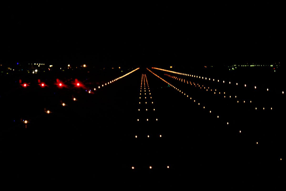
Below the DA/H or MDA/H there is no implicit obstacle protection. Designers check the visual segment, and an obstacle there may raise the visibility, remove the visual descent point or close the approach at night, but it is the pilot who sees and avoids obstacles from the minimum to touchdown.
Height above touchdown and above airport
FAA charts give each minimum twice: as an altitude above mean sea level and as a height. For straight-in minima the height is the height above touchdown (HAT), above the touchdown zone elevation (TDZE), the highest point in the first 3,000 ft of the landing surface. For circling it is the height above airport (HAA), above the airport elevation, the highest point of any usable runway. At Yakima the VOR/DME RWY 27 has a Category A MDA of 2,100 ft for both: a HAT of 1,032 ft (TDZE 1,068 ft) straight in and a HAA of 1,001 ft (airport elevation 1,099 ft) circling. ICAO charts print the height in brackets after the altitude, as in 2000 (1485), and French charts state the reference datum in the minima box.
Straight-in minima and chart notations
Straight-in minimums are published when the final approach course is within 30° of the runway alignment and a normal descent can be made from the charted altitudes. Otherwise only circling minima appear and the title carries a letter instead of a runway, as in VOR-A. A pilot with the runway in sight may still land straight in when cleared.
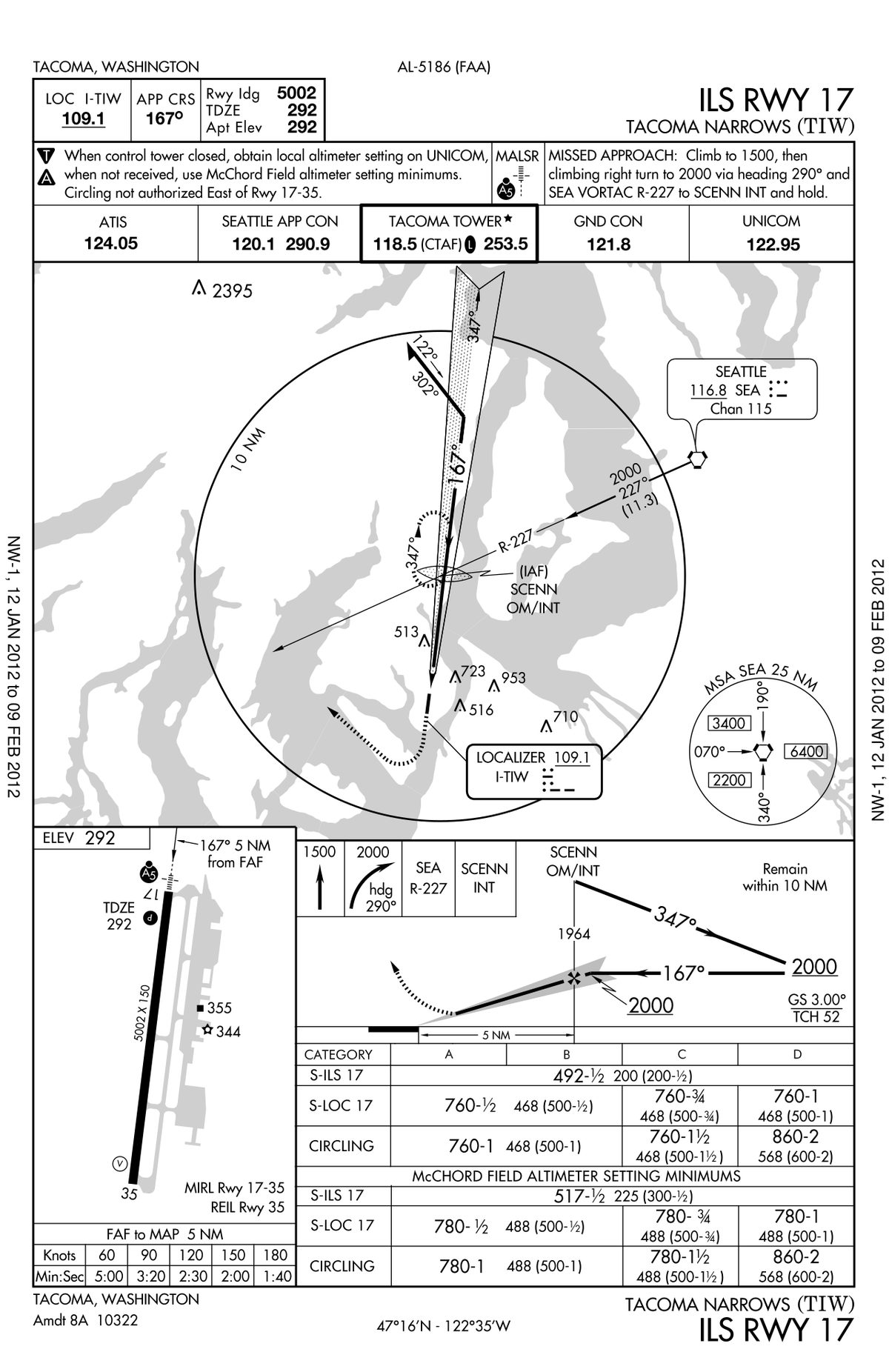
FAA minima read as altitude and visibility: 580-1 is an MDA of 580 ft with 1 statute mile, and 2100/60 an MDA of 2,100 ft with an RVR of 6,000 ft, given in hundreds of feet; figures in brackets are military minima. A chart may publish two sets of minima, one for aircraft able to identify a stepdown fix in the final segment and one for those that cannot, or one for a local and one for a remote altimeter setting.
NA means not authorised (14 CFR 97.3). It appears as "Procedure NA at night" where unlit obstacles penetrate the visual segment, as circling restrictions for a sector, as a symbol withdrawing alternate minima, and in notes such as "DME/DME RNP-0.3 NA" or a baro-VNAV temperature limit. Inoperative equipment matters too. The Yakima ILS or LOC RWY 27 notes, for example, raise the Category C and D localiser visibility to 2 SM when the approach lights are inoperative, and an item deferred under the aircraft's minimum equipment list, within its repair category (A as stated for the item, B 3 days, C 10 days, D 120 days), can remove a capability such as baro-VNAV or autoland and with it a line of minima.
Frequently asked questions
What is the difference between OCA/H and MDA/H?
The obstacle clearance altitude or height is a design figure, the lowest altitude or height at which the obstacle clearance criteria are met for an aircraft category. The minimum descent altitude or height is an operating minimum. It may never be lower than the OCA/H, and it is raised further where the system minimum for the navaid, the aircraft's flight manual or the operator's own procedures demand a higher value.
What is the minimum obstacle clearance on an instrument approach?
Under PANS-OPS the primary area of the initial approach segment gives 300 m (984 ft), a figure also used in holding areas and for the minimum sector altitude. The margin decreases in the intermediate and final segments and is built into the OCA/H of the final approach. In the missed approach it is 30 m, then 50 m in the final phase. The FAA's TERPS adds 250 ft to the controlling obstacle for an LNAV minimum descent altitude.
How are aircraft approach categories determined?
By the speed at the threshold at maximum certificated landing mass, VAT, which PANS-OPS takes as 1.3 VSO or 1.23 VS1G; the FAA uses VREF or 1.3 VSO. Category A is below 91 kt, B 91 to 120 kt, C 121 to 140 kt, D 141 to 165 kt and E 166 to 210 kt. An aircraft manoeuvring faster than its category's speed range should use the minima of the category matching that speed.
What is the difference between HAT and HAA?
Both are FAA chart figures. Height above touchdown (HAT) is the height of a straight-in DA or MDA above the touchdown zone elevation, the highest point in the first 3,000 ft of the landing surface. Height above airport (HAA) is the height of a circling MDA above the airport elevation, the highest point of any usable runway. At Yakima an MDA of 2,100 ft is a HAT of 1,032 ft straight in but a HAA of 1,001 ft circling.
Why is the OCH different for each aircraft category?
Faster aircraft need more room. Protected areas for turns and circling grow with speed, and on approaches with vertical guidance the designer adds an allowance for the height lost during the transition to the go-around, which depends on the category. Minima also depend on the missed approach climb gradient. PANS-OPS assumes 2.5%, and a steeper gradient can give lower published minima for aircraft that can achieve it.
Test yourself on Obstacle Clearance and Approach Minima
The v1prep banks cover this topic in General and Radio Navigation (061/062), with a worked explanation for every answer. EASA ATPL, PPL, IR and CPL, the FAA written tests and A320/B737 type ratings.
Start practising →Sources and further reading
- ICAO Doc 8168, Procedures for Air Navigation Services, Aircraft Operations (PANS-OPS), and Annex 6, Operation of Aircraft
- AIP France, ENR 1.5, Holding, Approach and Departure Procedures (aircraft categories, missed approach gradient, altimetric reference)
- FAA Aeronautical Information Manual, Chapter 5 Section 4, Arrival Procedures (TERPS approach types, minima, visual segment)
- 14 CFR 97.3, Symbols and terms used in procedures
- 14 CFR 91.175, Takeoff and landing under IFR
- FAA Pilot/Controller Glossary (touchdown zone elevation and related terms)
- EASA, Easy Access Rules for Air Operations (Regulation (EU) No 965/2012)
- FAA Instrument Procedures Handbook (FAA-H-8083-16B)
Library articles are written for study and exam preparation. They do not replace your aircraft's approved documentation, your operator's procedures or the regulations themselves.