Turn and Slip Indicators
The turn and slip indicator and the turn coordinator show the direction and rate of turn, measured by a spring-restrained rate gyro, and the balance of the turn, shown by a ball in a curved liquid-filled tube. The turn coordinator's canted gyro also responds to rate of roll.
The turn and slip indicator answers two questions at once: how fast is the aeroplane turning, and is the turn balanced? A gyro-driven needle measures the rate of turn, and a balance ball in a curved tube shows whether the aeroplane is slipping or skidding. Its successor in light aircraft, the turn coordinator, replaces the needle with a small aircraft symbol and responds to roll as well as to yaw.
Both instruments measure through precession rather than rigidity, with a gyro of their own, and in the typical light aeroplane they run on a different power source from the attitude and heading indicators. That independence is their value: when the vacuum-driven gyros fail in cloud, needle, ball and clock are what the pilot turns with. Europe's Part-NCO requires turn and slip indications at night and under IFR, and FAA 14 CFR 91.205(d) requires a slip-skid indicator and, with some exceptions, a gyroscopic rate-of-turn indicator for IFR flight.
Rate of turn and rate-one turns
Turn indicators are graduated in standard rates. A rate one turn, called a standard rate turn in FAA usage, is 3° per second: 180° in one minute, 360° in two. A rate two turn is 6° per second, a full circle in one minute. On the turn and slip indicator the first graduation either side of centre marks rate one, and some instruments have a second mark for rate two; on the turn coordinator the L and R marks show rate one, and the face is often marked "2 MIN".
The bank needed for rate one grows with true airspeed. European texts use the rule of thumb TAS ÷ 10 + 7; FAA material uses TAS ÷ 10 plus half that figure (see turning flight).
| TAS | Bank for rate one (TAS ÷ 10 + 7) | Radius of turn |
|---|---|---|
| 100 kt | About 17° | About 0.5 NM |
| 150 kt | About 22° | About 0.8 NM |
| 200 kt | About 27° | About 1.1 NM |
| 250 kt | About 32° | About 1.3 NM |
In a rate one turn the aeroplane covers a full circle in two minutes, so the circumference is the distance flown in two minutes and the radius is about TAS ÷ 190 in nautical miles, or TAS ÷ 200 as a rougher rule of thumb: about 1.9 NM at 360 kt. The bank for rate one becomes excessive at airliner speeds, so procedures cap it: ICAO holding assumes 25° or 3° per second, whichever needs less bank, and the FAA uses 3° per second, 30°, or 25° with a flight director (see holding patterns).
Turn and slip indicator
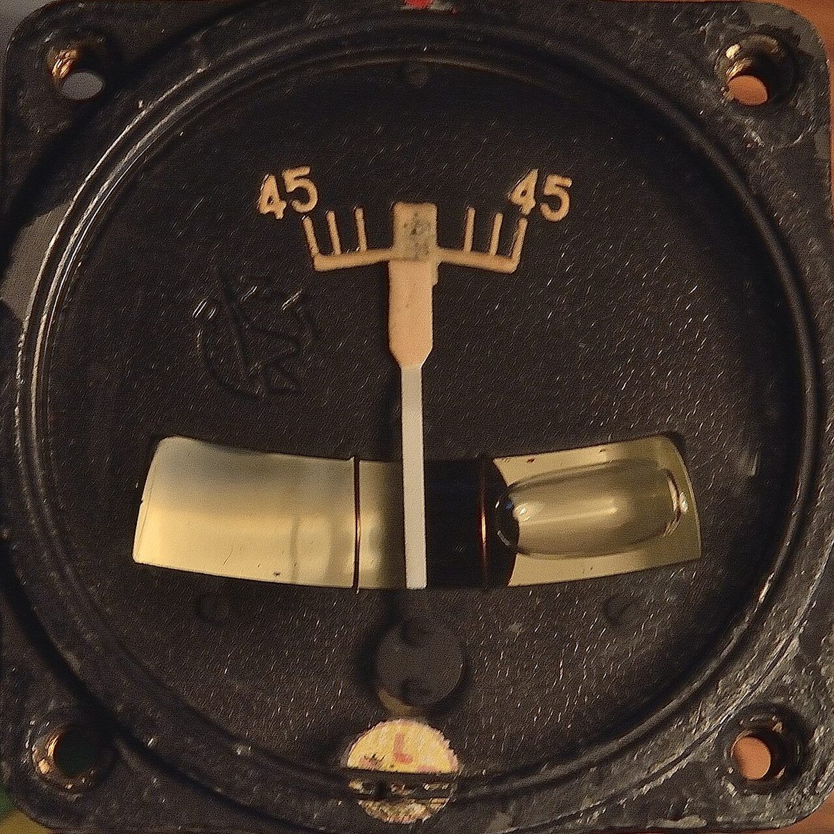
The classic turn and slip indicator, also known as the needle and ball, combines two separate instruments on one face:
- a rate-of-turn indicator, a rate gyro that measures the rate of turn about the aeroplane's normal axis and drives a needle left or right;
- a slip indicator, a simple inclinometer showing whether the bank is right for the rate of turn.
The needle shows only rate and direction of yaw. In a steady turn it is proportional to rate of turn; it says nothing about bank angle or pitch.
Yaw rate gyros
The turn needle is driven by a rate gyro, the kind of yaw rate gyro also used in yaw dampers (see yaw dampers and rudder limiting). Its rotor spins about a horizontal axis lying athwartships, in a single gimbal pivoted fore and aft, so the gyro has only one degree of freedom. A spring holds the gimbal centred.
When the aeroplane yaws, the case forces the gyro round with it. The gyro responds by precessing, tilting its gimbal about the fore-and-aft axis. The tilt stretches the spring, and the spring's force causes a second precession that turns the gyro with the aeroplane. The gimbal settles where that second precession exactly matches the rate of turn, so the tilt, and the needle geared to it, is proportional to the rate of turn (see gyroscopic principles). A roll with no yaw moves the gimbal about its own pivot and produces no reading.

Because it measures through precession, the rate gyro is spun slower than displacement gyros: a highly rigid rotor would precess too little to measure. The same principle explains its errors:
- Rotor speed. An air-driven turn indicator with a partly blocked filter runs slow and under-reads; the aeroplane turns faster than shown. An over-speeding rotor over-reads.
- Airspeed. The spring is calibrated for a design TAS; exam texts quote one manufacturer's figure of at most 5% error from 85 to 350 kt with calibration at 260 kt.
- Steep turns. With the gimbal already tilted, the pitching motion of a steep, level turn adds precession, so the indicator over-reads and may reach its stop.
- Stops. The gimbal is limited to a tilt corresponding to about 20° per second. With only one gimbal the gyro cannot topple, and it reads correctly again once the rate falls.
Turn coordinator
The turn coordinator uses the same spring-restrained, single-gimbal rate gyro, but with its gimbal axis canted at about 30° to the fore-and-aft axis. The gyro then senses rolling as well as yawing. As soon as the pilot rolls into a turn, before any steady yaw has developed, the miniature aircraft symbol banks, so the turn is anticipated rather than confirmed late.
The display is a small aircraft symbol seen from behind. Its wing tip against the L or R mark means a rate one turn to that side. The symbol's bank is not the aeroplane's bank angle: in a steady turn the instrument shows rate of turn, and only while the bank is changing does it add rate of roll. Because the symbol looks like an attitude indicator, the face carries the placard "NO PITCH INFORMATION".
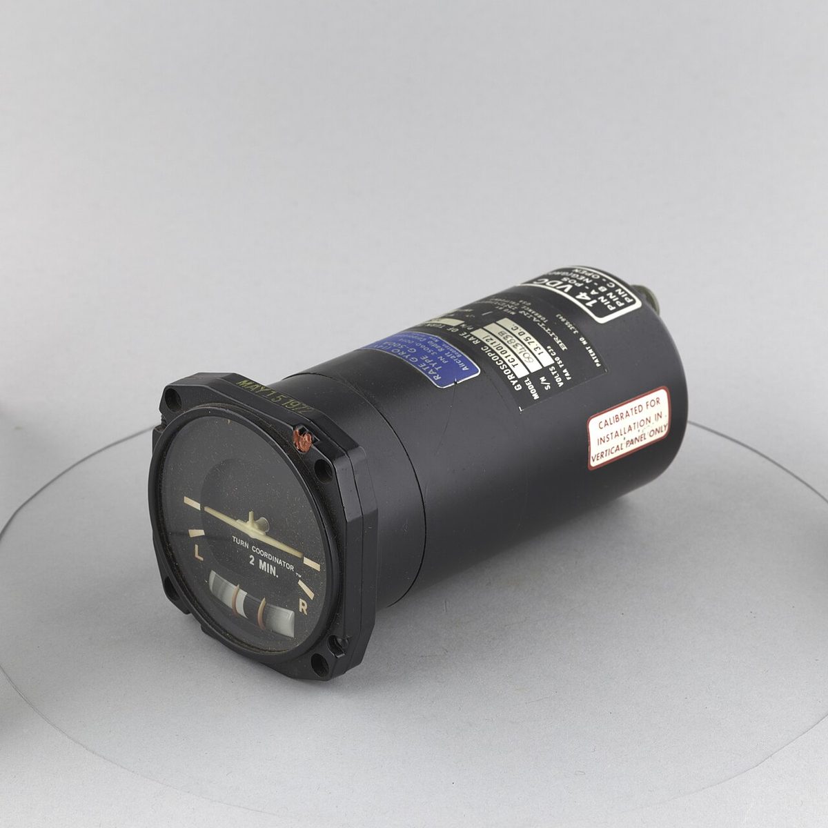
In the typical light trainer the turn coordinator is electric while the attitude and heading indicators are vacuum-driven, deliberately, so that a pump failure leaves one gyro working. On partial panel, a level symbol with the ball centred means no turn and no roll, so the wings are level; heading changes are then made with rate one turns timed on the clock.
Slip and skid indications
The slip ball, balance ball or slip-skid indicator is a solid ball in a curved glass tube filled with a damping liquid. It is a pendulum whose pivot is, in effect, the centre of curvature of the tube, and it needs no power at all. Older types used a small metal pendulum instead.
In a balanced, co-ordinated turn the resultant of weight and centrifugal reaction acts along the aeroplane's normal axis, parallel to the lift, and holds the ball in the centre between the two lines. When the bank and the rate of turn do not match, the resultant tilts and the ball rolls sideways.
| Condition | What is wrong | Ball | Correction |
|---|---|---|---|
| Balanced | Bank matches rate of turn | Centred | None |
| Slip | Too much bank for the rate of turn | Inside the turn | Rudder towards the ball, or less bank |
| Skid | Too little bank for the rate of turn | Outside the turn | Rudder towards the ball, or more bank |
The rule is step on the ball: press the rudder pedal on the side to which the ball has moved (see turning flight). On the ground an aeroplane cannot bank, so in a taxi turn the ball swings to the outside while the needle or symbol shows the turn, one of the pre-flight checks before an IFR departure.
Exam tip: read rate and balance separately. Needle on the first right mark with the ball out to the left is a rate one right turn with too little bank, a skid: add left rudder or more bank. Symbol on the L mark with the ball out to the left is a rate one left turn with too much bank, a slip: add left rudder or reduce the bank.
Glass cockpits keep the ball as a sideslip indicator. On the Boeing 737 primary flight display a slip/skid indication moves beneath the bank pointer and fills white at full-scale deflection. On the A320 the sideslip index plays the same role; after an engine failure the flight augmentation computers modify it to show the rudder for best climb performance, the beta target (see asymmetric flight).
Timed turns
A timed turn uses the clock and the turn indicator to change heading without a heading indicator. At rate one the time in seconds is the heading change divided by 3; at rate two, divided by 6.
| Heading change | Rate one | Rate two |
|---|---|---|
| 30° | 10 s | 5 s |
| 90° | 30 s | 15 s |
| 120° | 40 s | 20 s |
| 180° | 60 s | 30 s |
The technique is to establish the bank for rate one, start the clock, hold the needle or symbol on the mark with the ball centred, and roll out when the time is up. Once the wings are level and the speed steady, the magnetic compass confirms the new heading. A timed turn avoids the compass's turning errors altogether, and turning the shorter way matters: from 270° to 150° to the left is 120°, 40 seconds, not 80.
When the heading indicator fails under radar control, the FAA's no-gyro approach relies on the same skill. The controller says "turn left" and "stop turn", the pilot turns at standard rate and executes at once, and after the aeroplane has been turned onto final approach turns are made at half standard rate.
Warning: the turn indicator shows rate, not attitude. A steady altimeter does not prove the wings are level, because a balanced turn can hold altitude; in partial-panel flight keep the needle or symbol centred for straight flight and use the pressure instruments for pitch.
Frequently asked questions
What is a rate one turn?
A rate one turn, called a standard rate turn by the FAA, is a turn at 3 degrees per second, so 180 degrees takes one minute and a full circle two minutes. It is marked on the turn and slip indicator by the first graduation and on the turn coordinator by the L and R marks. The bank needed rises with true airspeed: about TAS divided by 10 plus 7 degrees, so 22 degrees at 150 knots.
What is the difference between a turn coordinator and a turn and slip indicator?
Both use a single-gimbal rate gyro restrained by a spring, and both have a slip ball. In the turn and slip indicator the gimbal axis is fore and aft, so a needle shows rate of yaw only. In the turn coordinator the axis is canted by about 30 degrees, so a banking aircraft symbol also responds to rate of roll and shows a turn beginning as soon as bank is applied.
Where does the ball go in a slip and in a skid?
In a slip the bank is too steep for the rate of turn and the ball moves to the inside of the turn. In a skid the bank is too shallow for the rate of turn, often from too much rudder into the turn, and the ball moves to the outside. In both cases step on the ball: apply rudder on the side the ball has moved to, or adjust the bank.
How long does a timed turn take?
At rate one, 3 degrees per second, divide the heading change in degrees by 3 to get seconds: 90 degrees takes 30 seconds and 180 degrees one minute. Start the clock when the bank is established, roll out when the time is up, then check the compass once the wings are level and the speed steady. Timed turns are used when the heading indicator has failed, because they avoid the compass's turning errors.
Why is a turn coordinator marked no pitch information?
Its miniature aircraft banks like the symbol of an attitude indicator, so a pilot under stress, or flying partial panel after an attitude indicator failure, might read it as an attitude display. It shows only the rate and direction of turn and, while the bank is changing, the rate of roll. The placard reminds the pilot that pitch must come from the altimeter, vertical speed and airspeed indicators.
Test yourself on Turn and Slip Indicators
The v1prep banks cover this topic in Instrumentation (022), with a worked explanation for every answer. EASA ATPL, PPL, IR and CPL, the FAA written tests and A320/B737 type ratings.
Start practising →Sources and further reading
- FAA Instrument Flying Handbook (FAA-H-8083-15B), Chapter 5, Flight Instruments (turn indicators)
- FAA Pilot's Handbook of Aeronautical Knowledge (FAA-H-8083-25), Chapter 8, Flight Instruments (turn indicators)
- FAA Aeronautical Information Manual, Chapter 5 Section 4 (5-4-11, no-gyro approach)
- 14 CFR 91.205, Instrument and equipment requirements (IFR instruments)
- EASA Easy Access Rules for Air Operations (Regulation (EU) No 965/2012), instruments and equipment (NCO.IDE)
- EASA, Explanatory Note to ED Decision 2018/001/R, Part-FCL theoretical knowledge learning objectives (022 Instrumentation)
Library articles are written for study and exam preparation. They do not replace your aircraft's approved documentation, your operator's procedures or the regulations themselves.