Boeing 787 Hydraulic System
The Boeing 787 hydraulic system consists of three independent systems, left, centre and right, operating at 5,000 psi. Engine-driven and electric motor-driven pumps power the left and right systems, two large electric pumps power the centre system, and the wheel brakes are electric.
The Boeing 787 keeps a conventional three-system hydraulic layout, left, centre and right, but runs it at 5,000 psi and powers the centre system electrically. Boeing's 2007 description of the 787 systems says the hydraulic system is similar to the one in the traditional architecture and that the key difference is the power source for the centre system: two large electric pumps instead of air-turbine-driven pumps.
Hydraulics also do less on the 787. The wheel brakes are electric, where the 777's are hydraulic, four of the fourteen spoilers are moved by electro-mechanical actuators, and the stabiliser trim is electrically actuated. What remains hydraulic is the list Boeing gave in 2007: the primary flight control actuators, the landing gear, nose gear steering, the thrust reversers and the high-lift devices.
This article draws on the FAA Master Minimum Equipment List (MMEL), the FAA Flight Standardization Board (FSB) reports, the EASA type-certificate data sheet (TCDS) and, for design intent, Boeing's 2007 AERO article on the no-bleed systems, written before the 787 entered service. General principles are in hydraulic pumps and power sources and hydraulic system principles and fluids.
Three systems at 5,000 psi
The three systems are independent. According to Boeing they collectively support:
- the primary flight control actuators;
- landing gear actuation;
- nose gear steering;
- the thrust reversers;
- the leading and trailing edge flaps.
The original FSB differences table lists the 787 hydraulic systems at 5,000 psi as a difference from the 777. Boeing's reason for the higher pressure is size: it allows smaller hydraulic components, saving both space and weight.
| System | Main power source | Additional pumps |
|---|---|---|
| Left | Engine-driven pump (EDP) on the left engine gearbox | One electric motor-driven pump (EMP) |
| Centre | Two large EMPs | None |
| Right | EDP on the right engine gearbox | One EMP |
Not counting the ram air turbine, that makes six pumps: two engine-driven and four electric. The MMEL agrees, listing six hydraulic pump FAULT lights, six pump pressure indication systems, six pump temperature indications and four EMP selectors.
For the 787-9 and 787-10, the TCDS specifies the hydraulic fluid as ExxonMobil HyJet V to BMS3-11 Type V Grade C only; for the 787-8 it refers to the applicable manuals. The TCDS also records, for all three models, an equivalent safety finding for a hydraulics bay in the aft strut fairing.
Left and right systems
The primary power source for the left and right systems is an engine-driven pump (EDP) on each engine's accessory gearbox. Both engine data sheets show the same gearbox arrangement, two variable frequency starter generators and one hydraulic pump, for the Rolls-Royce Trent 1000 and for the General Electric GEnx-1B. The GEnx data sheet allows the hydraulic drive a maximum power of 46.2 kW on the earlier models and 44 kW on the GEnx-1B/P2 models. Boeing described the 787's engine-driven pumps as similar to those of traditional aircraft. The MMEL lists an EDP depressurisation function for each of the two pumps.
In addition, each of these systems has an electric motor-driven pump (EMP), which Boeing described as being for peak demands and for ground operations. The EMP selectors have AUTO, ON and OFF positions according to the MMEL: four selectors in all, one each for the left and right EMPs and two for the centre system.
The centre system
The centre hydraulic system is where the 787 differs most from the traditional design. Boeing contrasted the two designs in 2007, before entry into service:
| Traditional centre system | 787 centre system | |
|---|---|---|
| Peak demand pumps | Two large air-turbine-driven pumps, about 50 gpm at 3,000 psi | Two large electric pumps, about 30 gpm at 5,000 psi |
| Rest of the flight | Two small electric pumps, about 6 gpm | One of the two large pumps |
| Use | Air-driven pumps for landing gear, high lift and flight controls during take-off and landing | One pump runs throughout the flight, the other only during take-off and landing |
The original FSB differences table confirms the result for pilots coming from the 777: no air-driven demand pumps, electric pumps instead. The pumps are named C1 and C2 in the MMEL. Each has its own common motor start controller (CMSC): the MMEL lists two CMSCs for the centre hydraulic system and, with one inoperative, treats its centre pump as inoperative too. In Boeing's 2007 description, the large hydraulic pump motors are among the loads of the ±270 V DC supply described in Boeing 787 electrical system.
Several landing gear and steering functions are tied to the centre system. The MMEL lists a reserve steering isolation system, a nose gear isolation system and an alternate gear extension isolation system, and with the centre system quantity indication inoperative it treats all three as inoperative. It also lists a nose landing gear accumulator with its charging valve and gauge. The MMEL relief for one inoperative centre EMP requires the slat and flap secondary modes and the main landing gear priority valve to be checked every flight day.
Exam tip: on the 787 the left and right systems have an engine-driven pump plus an electric pump each; the centre system has only electric pumps, two of them. There are no air-driven pumps anywhere, because there is no bleed air to drive them.
What hydraulics still power
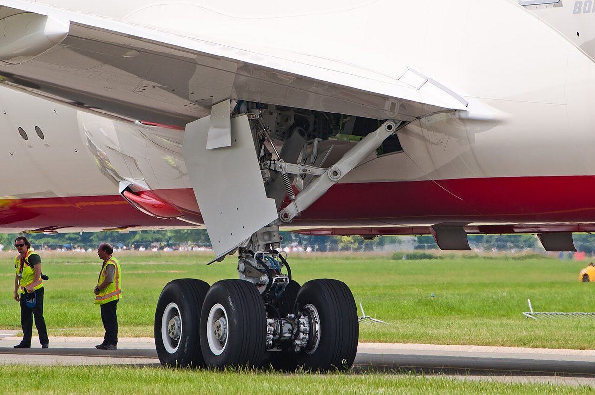
The three systems drive the primary flight control actuators and the high-lift devices described in Boeing 787 flight controls, the landing gear, nose gear steering and the thrust reversers. Other functions are wholly or partly electric:
| Function | Power on the 787 | Source |
|---|---|---|
| Wheel brakes | Electric | FSB 2011 differences table; MMEL ch. 32 |
| Spoilers 4, 5, 10 and 11 | Electro-mechanical actuators | MMEL 27-61-02 |
| Spoilers 1 to 3, 6 to 9, 12 to 14 | Hydraulic | MMEL 27-61-02 |
| Stabiliser trim | Electrically actuated | FSB 2011 differences table |
| Engine and APU starting | Electric (starter generators) | FSB 2011; airport planning document |
Several hydraulic loads are commanded by wire and powered by fluid. Nose wheel steering is one: the original FSB report describes the tiller as "steer by wire", and the MMEL lists a left and a right tiller, two nose wheel steering channels and three rudder pedal steering channels, while the steering itself is one of the hydraulic functions in Boeing's list. The flaps and slats are another: they are moved through a flap/slat hydraulic control module (HCM), for which the MMEL lists 14 solenoid coils and two power control channels, and the MMEL also lists flap and slat secondary modes and an alternate flap/slat control as back-ups. The landing gear has a hydraulic actuation system, nose and main gear bypass/auto-off valves with pressure transducers, and a separate alternate extend system.
The 787-10 adds a hydraulic item of its own: its certification tables list a semi-lever gear actuator with a hydraulic pressure transducer and a semi-lever gear isolation valve, the semi-levered main gear being a 787-10 feature in the FSB differences tables.
Electric brakes
The original FSB report lists electric brakes among the 777 to 787 differences, with brake system operation functionally equivalent, and the FAA's 777 report lists hydraulic brakes as a 777 difference when going from the 787-8 to the 777-300ER. The MMEL describes the installation:
- eight wheel brake systems, one per main gear wheel;
- 32 electric brake actuator systems, four per wheel, of which one per wheel may be inoperative for dispatch;
- eight antiskid control systems;
- a brake temperature monitor system and an autobrake system;
- two nose gear spin brakes.
The TCDS certification tables name a brake system control unit and an electric brake actuator controller. One indication changes accordingly: where the 777 shows a brake accumulator, the 787, according to the original FSB report, shows a battery indication. More on brakes in general is in wheel brakes.
Reservoirs, indications and abnormal cases
Each of the three systems has its own reservoir. The MMEL lists, for the three reservoirs, a reservoir accumulator with a charging valve and gauge, a reservoir pressure indication system, a reservoir temperature indication system and an auto-bleed valve; the provisos for the auto-bleed valves refer to air trapped in the reservoir. A remote reservoir quantity gauge is also listed. Boeing's pre-service 2007 article named the pressurisation of the hydraulic reservoirs, with engine cowl ice protection, as the only uses of bleed air on the 787; the later documents used here do not say how the reservoirs are pressurised.
On the flight deck, the MMEL lists a hydraulic synoptic display, a system pressure transducer for each system, pressure and temperature indications for each of the six pumps, quantity indications for each system, six pump FAULT lights and two pump ON lights. It also lists six pump case drain filter monitoring systems.
The ram air turbine (RAT) appears in the hydraulic power chapter of the MMEL, with a RAT switch carrying UNLKD (unlocked) and PRESS lights, a position indication system and two RAT heaters. The public sources used here do not describe what the RAT powers or which hydraulic system it serves.
For pilots converting from the 777, the current FSB report rates the hydraulic differences, controls and indicators and the systems themselves, at level A, self-instruction. The redundancy follows from the architecture: the left and right systems each have pumps driven from two different power sources, engine and electric, and the centre system has two electric pumps with separate controllers. The FSB report also notes that a flap extension failure on the 787 is extremely remote by system design, which is why a partial flap, rather than a no-flap, approach and landing is demonstrated in checks.
Frequently asked questions
How many hydraulic systems does the Boeing 787 have?
Three independent systems: left, centre and right. They operate at 5,000 psi and together power the primary flight control actuators, landing gear actuation, nose gear steering, the thrust reversers and the leading and trailing edge flaps. The left and right systems are powered mainly by engine-driven pumps, the centre system by two large electric pumps.
Why does the 787 use 5,000 psi hydraulics?
Boeing's 2007 description, written before entry into service, says the higher pressure lets the aircraft use smaller hydraulic components, saving both space and weight. The original FAA FSB report lists the 787 hydraulic systems at 5,000 psi as a difference from the 777. Boeing compared the 787's centre system pumps, about 30 gallons per minute at 5,000 psi, with traditional air-driven pumps of about 50 gallons per minute at 3,000 psi.
How is the 787 centre hydraulic system powered?
By two large electric motor-driven pumps, with no air-driven demand pumps. Boeing's pre-service 2007 article says one of them runs throughout the flight and the other only during take-off and landing, and places the large hydraulic pump motors on the ±270 V DC supply. The MMEL lists a common motor start controller for each of the two pumps.
Are the brakes on the 787 hydraulic?
No. The 787 has electric brakes, a difference the FAA FSB report lists against the 777, which has hydraulic brakes. The MMEL lists eight main wheel brake systems with 32 electric brake actuators, four per wheel, and eight antiskid control systems. Where the 777 shows a brake accumulator indication, the 787 shows a battery indication.
How many hydraulic pumps does the Boeing 787 have?
Six, not counting the ram air turbine: one engine-driven pump on each engine for the left and right systems, one electric pump in each of those systems, and two electric pumps for the centre system. The MMEL agrees, listing six hydraulic pump FAULT lights, six pump pressure indications and four electric pump selectors.
Test yourself on Boeing 787 Hydraulic System
The v1prep banks cover this topic in the 787 type-rating bank, with a worked explanation for every answer. EASA ATPL, PPL, IR and CPL, the FAA written tests and A320/B737 type ratings.
Start practising →Sources and further reading
- Boeing AERO magazine, Q4 2007, M. Sinnett, 787 No-Bleed Systems: Saving Fuel and Enhancing Operational Efficiencies
- FAA Master Minimum Equipment List, Boeing 787, Revision 19 (20 May 2025)
- FAA Flight Standardization Board Report, Boeing 787 (original report, 25 August 2011)
- FAA Flight Standardization Board Report, Boeing 787, Revision 7 (8 May 2019)
- FAA Flight Standardization Board Report, Boeing 777, Revision 12 (draft), 787-8 to 777-300ER differences
- EASA Type-Certificate Data Sheet EASA.IM.A.115, Boeing 787-8, 787-9 and 787-10, Issue 30
- EASA Type-Certificate Data Sheet IM.E.102, General Electric GEnx series, Issue 12
Library articles are written for study and exam preparation. They do not replace your aircraft's approved documentation, your operator's procedures or the regulations themselves.