A320 Communications and Datalink
The A320 communication system comprises the VHF and optional HF transceivers, the radio management panels that tune them, and the audio management unit with its audio control panels that route audio to and from each crew station, complemented by a datalink system that exchanges messages with the airline and ATC.
The A320 separates two jobs that a light aircraft radio combines. Radio management panels (RMPs) tune the transceivers; audio control panels (ACPs), working through the audio management unit (AMU), decide what each crew member hears and where each microphone transmits. A frequency set on an RMP is therefore not heard until its reception knob is opened on an ACP. A datalink system adds written exchanges with the airline and ATC, shown on the MCDU and on a dedicated display, the DCDU.
The system serves internal communication, between the flight crew, other cockpit occupants, cabin crew, ground crew and passengers, through the flight, cabin and service interphones and the passenger address (PA); and external communication, by VHF, HF or satellite (SATCOM), in voice or data mode. The cabin side is described in A320 cabin systems and CIDS, the radio principles in VHF, HF and satellite communications.
Communication system overview
The communications system comprises the VHF and HF transceivers, the radio tuning system (the RMPs) and the audio integrating system (the AMU and the ACPs).
There are two identical VHF systems, a third being optional, each with a transceiver in the avionics compartment and an antenna on the fuselage: VHF 1 on top of the forward fuselage, VHF 2 underneath at the rear and VHF 3 on top at the rear. They cover 118.0 to 136.975 MHz. Two HF systems are optional, covering 2.8 to 24 MHz, each with a transceiver, a coupler in the aft fuselage and an antenna in the fin. When HF is used on the ground, nobody may stand near the antenna, and HF must not be used during refuelling.
Only VHF 1 works in the emergency electrical configuration. The SOP therefore uses VHF 1 for ATC, VHF 2 for ATIS and company frequencies, and leaves VHF 3 to the datalink.
SELCAL tells the crew, aurally and visually, that a ground station is calling with the aircraft's code: the transmission key of the radio concerned flashes and a buzzer sounds until reset with the RESET key on the ACP (or the MASTER CAUT pushbutton). The aural alert is inhibited during take-off and landing.
Radio management panels
Two RMPs are on the pedestal and a third on the overhead panel. They give the crew control of all VHF (and HF) transceivers and back up the FMGCs for radio navigation. Each RMP can control any transceiver, and each is updated with the selections made on the others. RMP 1 and RMP 2 are connected directly to the transceivers; RMP 3 reaches them through RMP 1 and RMP 2, even when one of them is off.
Pressing a radio selection key, which then shows a green light, displays that radio's frequency in the ACTIVE window and its standby frequency in the STBY/CRS window. The concentric knobs set the standby value, the outer for whole numbers, the inner for decimals, and the transfer key swaps the two windows, tuning the radio to the new active frequency. The AM key selects AM on an HF set, whose default is single side-band (SSB), and the ON/OFF switch powers the panel.
The amber SEL light comes on, on both RMPs, when a transceiver normally associated with one RMP is tuned from another, for example VHF 1, normally RMP 1's, tuned from RMP 2. If one RMP fails, the remaining one controls all the transceivers, except that without RMP 3 a VHF 3 connected to ACARS can then be tuned only in data mode, by ACARS. In the emergency electrical configuration only RMP 1 works.
RMP radio navigation backup
The NAV key, under a transparent guard, engages the RMP radio navigation backup mode. It takes control of the VOR, ILS, GLS, MLS and ADF receivers away from the FMGCs and gives it to the RMPs; its green light comes on, and a second press returns control to the FMGCs. The STBY/CRS window can then show a course. The mode exists for the loss of both FMGCs (see A320 FMGS and MCDU).
Selecting backup on one RMP removes navaid tuning from both FMGCs, while the communication radios stay selectable as usual. The captain's RMP then controls VOR 1 and ADF 1. Either RMP can tune the ILS, GLS or MLS, provided STBY NAV is selected on RMP 1 and RMP 2. RMP 3 has no navigation role: its NAV key does nothing. When an ILS/DME is tuned from an RMP, the PFDs do not show the DME distance. With an ADF selected, the BFO key helps with the audio identification.
Audio control panels and AMU
The audio management system lets the crew use all radio communication and navigation facilities, the interphones, the call systems and the PA. It comprises the Audio Management Unit (AMU), three ACPs (a fourth and fifth are optional), jacks and sockets including one at the ground power receptacle, boomsets and hand microphones, three oxygen mask microphones, a radio push-to-talk switch on each sidestick, the SELCAL code panel and two cockpit loudspeakers with separate volume controls.
Each ACP has a row of transmission keys, one per radio, interphone and the PA, and reception knobs for listening:
- A reception knob pressed and released to the out position switches reception on; turning it sets the volume.
- A transmission key selects the channel the microphone will use; the CAB and PA keys show three green lines when selected.
- A flashing key announces a call: an external key for SELCAL, INT with the MECH light for the ground crew, CAB with the ATT light for the cabin crew. MECH and ATT go out after 60 s if not reset.
- The SELCAL/CALL RESET key cancels the buzzer.
- The VOICE filter key inhibits the most common navaid identification signals, VOR and ADF.
To hear the DME audio of an ILS station, the LS pushbutton on the FCU must also be on. The loudspeaker knob sets the volume of radio communications only: it does not control aural alerts and voice messages. If acoustic feedback (the Larsen effect) occurs, the crew reduce the loudspeaker volume but keep it loud enough to hear the radio.
The AUDIO SWITCHING selector handles a failure of audio channel 1 or 2, whether in an ACP or in the AMU. At NORM each pilot uses his or her own equipment; at CAPT 3 or F/O 3 that pilot keeps the acoustic equipment but uses the third occupant's ACP, who loses access to it. The green AUDIO 3 XFRD memo appears whenever the selector is not at NORM.

Transmit and interphone switches
The INT/RAD switch on each ACP has three positions. Held at RAD, it keys the boomset or oxygen mask microphone on the channel selected on the ACP, and returns to the off position when released. At INT it latches, keeping the microphone live on the interphone until another position is selected.
The sidestick radio selector has the same function as the INT/RAD switch. In its spring-loaded neutral position the boom and mask microphones are dead, while reception is normal. Squeezed to RADIO, they transmit through the equipment selected on the ACP. If RADIO is selected on the sidestick while the INT/RAD switch is at INT, radio has priority.
The flight interphone, hosted by the AMU, links the flight crew with each other and with the ground crew, through boomsets, hand microphones or mask microphones; a mechanic plugs into the FLT INT jack on the panel in front of the nose landing gear bay. To use it, a pilot opens the INT reception knob, presses the INT transmission key and then transmits with a push-to-talk switch or the INT/RAD switch. The cabin interphone, service interphone and PA are hosted by the cabin system.
VHF 3 and datalink
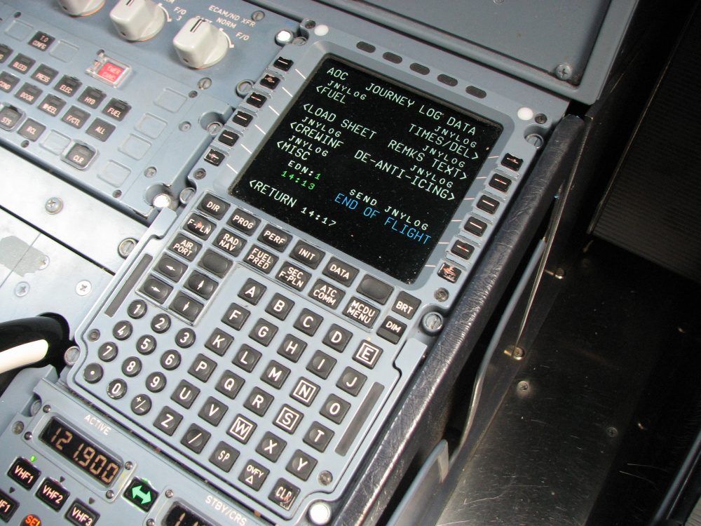
The datalink serves two families of applications: AOC applications, messages with the airline's operations centre, customised by each operator (flight logs, delay messages, weather and NOTAM requests, loadsheet requests, ETA and diversion messages), and ATC applications, which give communication, navigation and surveillance services for air traffic management. Exchanges are uplinks or downlinks, automatic or made by the crew on the DCDU, the MCDU or the RMP.
The Air Traffic Service Unit (ATSU) controls all datalink communication: it hosts the AOC and ATC applications and router services, and selects the best available medium among VHF, HF and SATCOM. The datalink primarily uses VHF 3, the router choosing the frequency from the aircraft position according to the VHF scan mask, a list of service providers in the airline's order of priority, ARINC and SITA being the two main worldwide networks. The scan mask is compulsory; without it the ECAM shows DATALINK ATSU FAULT. It is set on the VHF3 SCAN SELECT page and should not be modified unless the crew are told to, as a change can lose the datalink and raise the provider's charges.
VHF 3 can be used for voice after a failure of VHF 1 or VHF 2, or for airline-specific functions. Where ACARS is installed, VHF 3 must not be used for voice with ATC unless VHF 1 and VHF 2 are inoperative; the green VHF 3 VOICE memo shows that VHF 3 is in voice mode and ACARS communication interrupted. HF can also carry data, as an alternative to VHF 3 and SATCOM, the crew switching between data and voice on the RMP. SATCOM carries voice and data through satellites and ground earth stations.
Green ECAM memos report datalink events: COMPANY MSG for a message from the ground, COMPANY CALL or ACARS CALL for a request to call the company by voice on VHF, and COMPANY ALERT, which pulses for 180 s with a 1 s buzzer, for an alert message or an AOC condition needing crew action.
DCDU and ATC messages
A Datalink Control and Display Unit (DCDU) on each side displays the uplink and downlink messages and lets the crew control the exchange; messages shown on it can be printed. The ATC MSG pushbutton, one on each side of the glareshield, gives an aural and visual alert when an uplink arrives and is pressed to stop it. The MCDU manages the AOC and ATC functions and sends data to the DCDU.
FANS A applications, for remote and oceanic areas, comprise notification, controller-pilot data link communications (CPDLC) and automatic dependent surveillance contract (ADS-C), over the ACARS network. FANS B, for high-density continental airspace, offers notification and CPDLC over the Aeronautical Telecommunication Network (ATN). FANS A+ and B+ add departure clearance, oceanic clearance and D-ATIS, with datalink recording. ADS-B is broadcast by the Mode S transponder, not by the ATC datalink.
A route clearance arrives with the ATC MSG alert. The crew press ATC MSG, then on the DCDU select STBY, SEND and LOAD; LOAD SEC OK confirms that the route is in the secondary flight plan. If it is acceptable, they answer WILCO and activate the secondary. To change it, they modify the secondary, reply UNABLE and send a new request.
Voice remains a primary means of communication. The crew revert to voice in an emergency, when in doubt about a datalink message, when an operational timer times out or when a response has not been correctly transmitted. In an emergency descent ATC is told by voice, or by CPDLC if voice contact cannot be established. ATC datalink needs the clock within ±1 s of UTC, or messages may be rejected or obsolete ones accepted, so for FANS operations the crew do not set the clock manually (see controller-pilot data link communications).
Frequently asked questions
What is the difference between the RMP and the ACP on the A320?
The radio management panel (RMP) tunes: it sets the active and standby frequencies of the VHF and HF transceivers and, in backup, the navigation receivers. The audio control panel (ACP) works through the audio management unit and decides what each crew member hears and on which channel the microphone transmits. A frequency set on an RMP is not heard until its reception knob is opened on the ACP.
When is the RMP NAV backup used on the A320?
The NAV key, under a transparent guard, engages the radio navigation backup mode: it takes control of the VOR, ILS, GLS, MLS and ADF receivers away from the FMGCs and gives it to the RMP. It is meant for the case where both FMGCs have failed. Selecting it on one RMP removes navaid tuning from both FMGCs. RMP 3 cannot be used, and the communication radios remain selectable normally.
What is VHF 3 used for on the A320?
VHF 3 is normally devoted to the datalink (ACARS). Where ACARS is installed it should not be used for voice with ATC unless VHF 1 and VHF 2 are inoperative; it can be switched to voice after a failure of VHF 1 or VHF 2, or for airline-specific functions. When VHF 3 operates in voice and ACARS communication is interrupted, the green VHF 3 VOICE memo appears on the ECAM.
What is the DCDU on the A320?
The Datalink Control and Display Unit (DCDU), one on each side, displays the uplink and downlink messages exchanged with ATC and lets the crew control the exchange: answering, sending and loading a route clearance into the secondary flight plan. An incoming message is announced by the ATC MSG pushbutton on the glareshield, which the crew press to stop the alert.
Which radios work in the A320 emergency electrical configuration?
In the emergency electrical configuration only RMP 1 works and only VHF 1 is powered, so VHF 1 is the only transceiver that can be used. The SOP therefore assigns VHF 1 to ATC, VHF 2 to ATIS and company frequencies and VHF 3 to the datalink. RMP 1 is wired directly to all transceivers, but the others have no power.
Test yourself on A320 Communications and Datalink
The v1prep banks cover this topic in the A320 type-rating bank, with a worked explanation for every answer. EASA ATPL, PPL, IR and CPL, the FAA written tests and A320/B737 type ratings.
Start practising →Sources and further reading
- ICAO Annex 10, Aeronautical Telecommunications (Volume II, communication procedures; Volume III, communication systems)
- ICAO Doc 10037, Global Operational Data Link (GOLD) Manual (copy on SKYbrary)
- SKYbrary, Aircraft Communications, Addressing and Reporting System (ACARS)
- SKYbrary, Controller Pilot Data Link Communications (CPDLC)
- FAA Aeronautical Information Manual, Chapter 5 Section 3 (5-3-1, CPDLC and data link)
- EASA Easy Access Rules for Air Operations (Regulation (EU) No 965/2012), CAT.IDE.A.170, 175 and 180 (flight crew interphone, crew member interphone, public address) and CAT.IDE.A.195 (data link recording)
- EASA Type Certificate Data Sheet EASA.A.064, Airbus A318, A319, A320, A321
Library articles are written for study and exam preparation. They do not replace your aircraft's approved documentation, your operator's procedures or the regulations themselves.