Airbus A220 Fly-by-Wire Flight Controls
The A220 has fly-by-wire flight controls: the pilots' side-stick and rudder pedal inputs are sensed electronically and processed by three primary flight control computers (PFCCs), which work in a normal mode or a direct mode, both with a high angle-of-attack protection, while slats and flaps have their own electronic control unit with two slat and two flap channels.
The Airbus A220 is a fly-by-wire aircraft. The pilots fly it with side-sticks on the outboard consoles, and their inputs, with those of the rudder pedals, are sensed electronically and processed by three primary flight control computers (PFCCs). The system works in a normal mode and a direct mode and provides envelope protections; the slats and flaps are commanded separately through a slat/flap electronic control unit.
The A220 was designed by Bombardier, and its fly-by-wire system is not the A320's: one visible difference is that pitch trim is manual in manual flight. This article draws on the EASA type-certificate data sheet, the Transport Canada (TCCA) MMEL and evaluation report and the FAA Flight Standardization Board report. The general principles are in fly-by-wire, primary flight controls and spoilers and speed brakes.
A fly-by-wire design
The FAA report describes "Fly-By-Wire (FBW) technology controlled by dual sidesticks". EASA's certification basis for both models includes special conditions and an equivalent safety finding that bear on it:
| EASA special condition or finding | Subject |
|---|---|
| B-03 | Motion and effects of cockpit controls |
| B-04 | Static stability and low energy awareness |
| B-05 | Flight envelope protection design |
| B-17 | Normal load factor limiting system |
| C-08 | Pilot limit forces and torques (side-stick) |
| D-16 | Control surface position awareness and electronic flight control system (EFCS) |
| B-24 (equivalent safety finding) | Out of trim |
The three computers are PFCC 1, PFCC 2 and PFCC 3. Each has a cut-out switch, under a guard, on the overhead panel, with an OFF light. The MMEL allows dispatch with any one of them deactivated provided the other two work. With PFCC 3 deactivated it adds a condition: the APU must run throughout the flight with its generator verified working. The MMEL lists an advisory, PFCC 1 (2, 3) FAIL, and a status message, PFCC 1 (2, 3) OFF; dispatch with a FAIL message requires that computer to be selected OFF.
The MMEL's fault messages show where the PFCCs take their inputs: the air data systems, the inertial reference systems, the radio altimeters, the slat/flap electronic control unit (SFECU), the engine FADECs, the landing gear unit (LGSCU), the brake data concentrator units (BDCU), the wing anti-ice system and the FMS. An alternate flight control unit (AFCU) also receives inputs from the data concentrator unit module cabinets (DMC) and the SFECU. Side-stick and rudder pedal sensors each have their own redundancy messages.
Side-sticks and priority
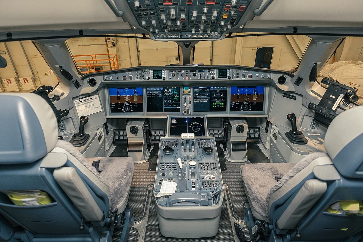
Each side-stick carries a stick shaker and an autopilot detent, as well as push-to-talk and intercom switches. The stick shakers matter for dispatch: with one inoperative, the pilot flying must use the side-stick whose shaker works. Dispatch with an autopilot detent inoperative excludes autoland.
Side-stick priority is managed with a SIDESTICK priority switch on each side of the glareshield, fitted with an arrow light and a PTY light, and the priority function includes an audio voice message. If one switch's lights fail, the MMEL requires the priority function on both sides, the other switch's lights and the voice message on both sides to be checked working before each flight.
Normal and direct modes
TCCA and the FAA list the fly-by-wire system, "normal and direct modes and associated envelope protections or degradations", as a special emphasis area in initial and recurrent ground training. In flight training, pilots must practise in PFCC direct mode: stall prevention, steep turns and a visual or instrument approach ending in a landing in direct mode. Both reports state that this can only be done in a full flight simulator, and both state that the A220 has no specific flight characteristics.
The FAA's Build 8.0A3 difference table describes the protections mode by mode: in normal mode, the "pitch protection functions" and a high angle-of-attack protection; in direct mode, a high angle-of-attack protection as well. In both modes a single "SPEED" aural alert sounds, inhibited below 30 ft radio altitude on landing.
Normal mode 2.20
In October 2022 TCCA evaluated an update of the control laws, normal mode (NM) 2.20, which replaced NM 2.19 on aircraft with modification 270020 or service bulletin BD500-270020 and AFM revision 20 or later. It brought three changes:
- Wing Drag Optimization (WDO): in climb and cruise, with flaps at 0, both ailerons deploy symmetrically 2 degrees trailing edge down to reduce drag inside the WDO envelope. WDO switches off at high speed, to reduce airframe loads, and below VMINTRIM.
- Pitch Attitude Protection (PAP): below 130 kt the nose-up pitch attitude limit depends on the slat/flap setting and the flight phase and falls as speed falls, to a minimum of 17 degrees at low speed. A positive pitch rate or a deceleration can lower it further.
- Ground lift dumping (GLD): the ailerons now deflect 25 degrees trailing edge up when ground lift dumping activates on landing.
The same update modified the procedures for the FLAP FAIL, SLAT FAIL, SLAT SKEW and SLAT-FLAP FAIL cautions, a jammed slat/flap lever and the HYD 1-3 and HYD 2-3 LO PRESS cautions. TCCA classed the training as Level A.
Exam tip: with NM 2.20 the ailerons droop 2 degrees in climb and cruise (WDO), deflect 25 degrees trailing edge up with ground lift dumping, and the nose-up pitch attitude limit bottoms out at 17 degrees.
Surfaces and actuators
The Airbus Aircraft Characteristics name the surfaces in their area tables: ailerons, flaps and spoilers in the wing (ESDU reference area 112.3 m²), the elevator in the 36.6 m² horizontal tail and the rudder in the 28.2 m² vertical tail, the same on both models. The slats appear in the MMEL's slat channels and cautions. The MMEL calls the actuators power control units (PCUs), with an INFO message PRIM PCU FAULT, and lists remote electronic units (REUs) in the spoiler system. EASA's special condition D-16 deals with control surface position awareness, and the flight control synoptic page is one of the formats the pilots can display.
Spoilers
The wing carries two kinds of spoiler, the multi-function spoilers (MFS) and the ground spoilers (GS), and the MMEL ties them together. The ground spoiler system may be inoperative for dispatch only with all multi-function spoiler surfaces working, and the MFS 1 system (an REU with left and right PCUs) only with the ground spoiler system working. Both reliefs exclude steep approaches.
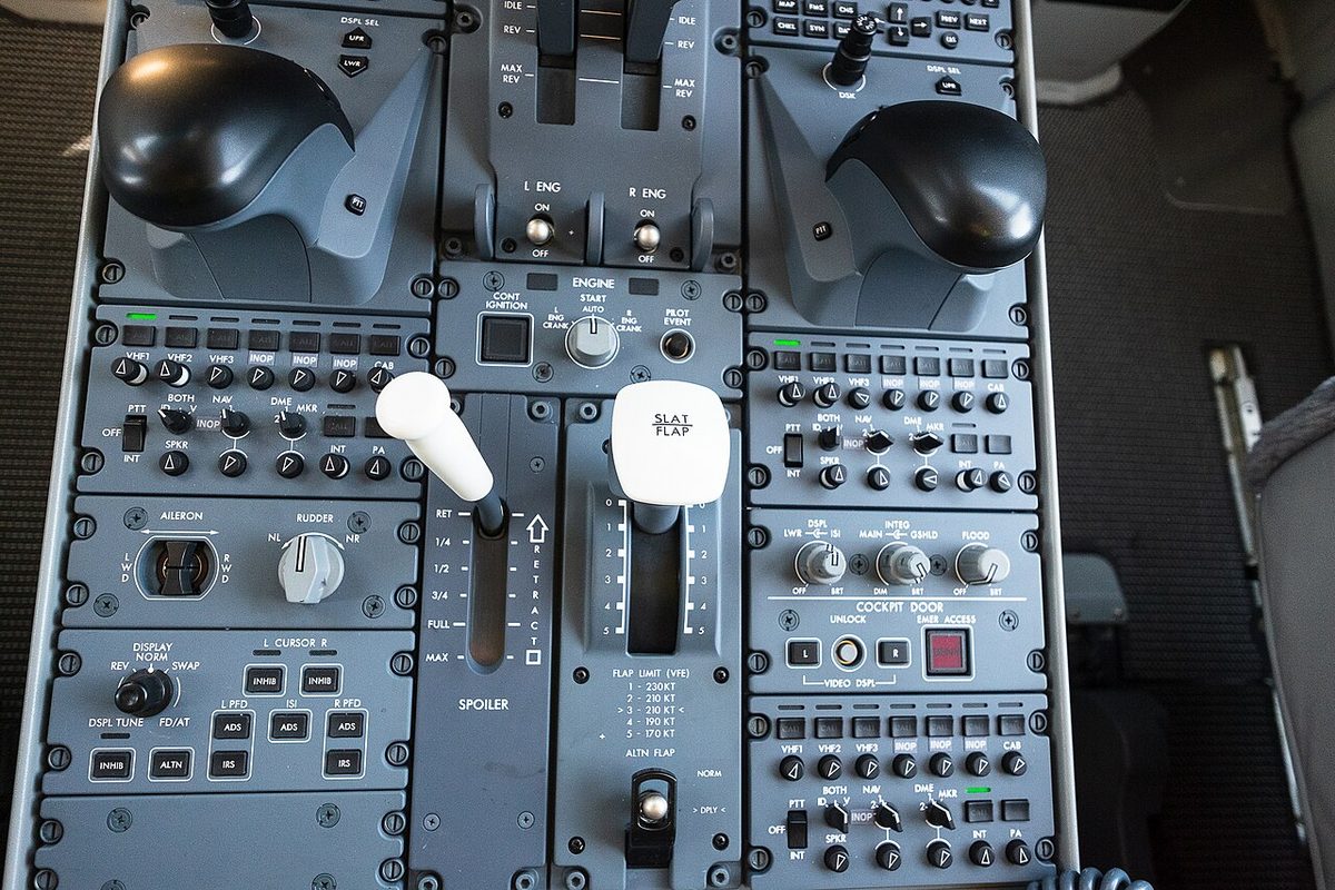
The crew's spoiler control is the SPOILER lever on the pedestal, marked RET, 1/4, 1/2, 3/4, FULL and MAX in the picture below. Rücker and Scholz mention adding spoilers to increase the rate of descent in an Emergency Descent Mode descent. The lever's sensors are monitored (SPOILER LEVER SNSR REDUND LOSS), and since Build 8.0A2 the SPOILER DEGRADED caution procedure includes a check of whether any multi-function spoiler is deployed. On landing, ground lift dumping (GLD) activates, and with NM 2.20 the ailerons join it, 25 degrees trailing edge up.
Slats and flaps
The SLAT/FLAP lever, which the MMEL calls the high lift select lever (HLSL), has positions 0 to 5. Its position sensors (RVDTs) are paired with the channels of the slat/flap electronic control unit (SFECU), which has two slat channels and two flap channels. With one channel deactivated, the slats or flaps it serves move at half speed and the SLAT SLOW or FLAP SLOW advisory appears. Faults of the slat and flap PDUs, skew sensors and outboard brake proximity sensors are reported through SLAT FAULT and FLAP FAULT messages. The ALTN FLAP switch below the lever is used when the lever has failed: since Build 8.0A3 the SLAT SLOW and FLAP SLOW advisories also appear when the lever has failed and ALTN FLAP is selected before engine start.
The normal landing flap settings are flap 4 and flap 5 for both models, and flap retraction and extension follow the flap reference (F) speeds displayed on the PFD and HUD. The flap limit (VFE) placard photographed on the pedestal of an airBaltic A220-300 (picture above) gives 230 kt at position 1, 210 kt at 2 and 3, 190 kt at 4 and 170 kt at 5; the AFM of each aircraft is the reference.
| Failure | Landing lever position (since Build 8.0A2) |
|---|---|
| FLAP FAIL with flaps at 0 or 1, no SLAT SKEW | 2 (previously 4) |
| HYD 1-3 LO PRESS with flaps at 0 or 1 | 2 |
Selecting 2 for landing means the lever does not have to move for a go-around. For training a zero-flap or zero-slat approach in the real aircraft, TCCA requires a lever position 1 approach to a missed approach, without pulling circuit breakers or depressurising hydraulic systems; in the simulator the approach continues to a landing. The two authorities differ on checking: TCCA judges a flap or slat extension failure extremely remote by design and does not require a no-flap landing in the proficiency check, while the FAA judges a flap extension failure not extremely remote and requires a no-flap approach and landing to be demonstrated for pilot certification.
Protections
EASA's special conditions B-05 (flight envelope protection) and B-17 (normal load factor limiting) frame the protections; the public sources describe some of them:
- High angle-of-attack protection, in normal and direct mode, with the "SPEED" aural alert.
- Pitch attitude protection, with its 17 degree low-speed floor under NM 2.20.
- Overspeed protection: TCCA and the FAA accept a demonstration of it in place of buffet boundary (tuck and Mach buffet) training.
- Normal load factor limiting, under its own EASA special condition.
TCCA's training emphasis also covers the appropriate use of the aircraft symbol versus the flight path vector in stall and upset recovery.
Trim
On the A220 the pilot trims in pitch during manual flight. Rücker and Scholz describe this as more conventional and easier to adapt to for pilots coming from conventional aircraft, while the A320 trims automatically and reduces workload. The MMEL lists left and right pitch trim switches and an aileron trim switch, and the pedestal carries an aileron and rudder trim panel. The horizontal stabiliser trim is set in units; the Airbus de-icing procedure sets it to 5 units before spraying and back to the take-off setting afterwards. The FAA lists runaway and jammed stabiliser training as not applicable to the A220 because of its design, and an EASA equivalent safety finding (B-24) covers the out-of-trim requirement.
Frequently asked questions
Does the A220 have fly-by-wire flight controls?
Yes. The FAA describes fly-by-wire technology controlled by dual side-sticks, and EASA certified the type with special conditions for flight envelope protection, normal load factor limiting, side-stick forces and electronic flight control systems. Three primary flight control computers (PFCC 1, 2 and 3) are installed, each with a cut-out switch on the overhead panel, and the system works in a normal mode and a direct mode.
What is direct mode on the A220?
Direct mode is the second of the two fly-by-wire modes named in the TCCA and FAA reports, which make the normal and direct modes, with their protections or degradations, a special emphasis item in ground training. In the full flight simulator, and only there, pilots must practise stall prevention, steep turns and an approach ending in a landing in PFCC direct mode. A high angle-of-attack protection is also described for direct mode.
How does side-stick priority work on the A220?
Each pilot has a SIDESTICK priority switch on the glareshield, fitted with an arrow light and a PTY light, and the priority function includes an audio voice message. The MMEL allows dispatch with one switch's lights inoperative only if the priority function on both sides, the other switch's lights and the voice message on both sides are checked working before each flight.
Is the A220 trimmed automatically like the A320?
No. Rücker and Scholz point out that the A220 is trimmed manually in manual flight, which is more conventional and easier to adapt to for pilots coming from conventional aircraft, whereas the A320 trims itself and reduces manual-flying workload. The MMEL lists left and right pitch trim switches and an aileron trim switch, and the FAA notes that runaway and jammed stabiliser training does not apply to the A220 because of its design.
What changed with the A220 fly-by-wire normal mode 2.20?
The control law update NM 2.20, fitted with modification 270020 or service bulletin BD500-270020, added Wing Drag Optimization, which droops both ailerons 2 degrees in climb and cruise with flaps at 0, refined pitch attitude protection to a minimum nose-up limit of 17 degrees at low speed, and deflects the ailerons 25 degrees trailing edge up when ground lift dumping activates on landing. TCCA classed the training as Level A.
Test yourself on Airbus A220 Fly-by-Wire Flight Controls
The v1prep banks cover this topic in the A220 type-rating bank, with a worked explanation for every answer. EASA ATPL, PPL, IR and CPL, the FAA written tests and A320/B737 type ratings.
Start practising →Sources and further reading
- EASA Type-Certificate Data Sheet EASA.IM.A.570, BD-500 (A220-100 and A220-300), Issue 25
- Transport Canada, Master Minimum Equipment List BD-500 (A220-100/-300), Issue 015
- Transport Canada, Operational Evaluation Report BD-500 (A220-100 and A220-300), Revision 3
- FAA Flight Standardization Board Report, Airbus Canada (formerly Bombardier) BD-500-1A10/-1A11 (A220-100/-300), Revision 3 (draft)
- Airbus, A220 Aircraft Characteristics Publication (ACP), BD500-3AB48-13800-00
- J. Rücker and D. Scholz, Highlights of the Airbus A220 from a Pilot's Perspective, HAW Hamburg, 2024
Library articles are written for study and exam preparation. They do not replace your aircraft's approved documentation, your operator's procedures or the regulations themselves.