Radio Altimeter
A radio altimeter, also called a radar altimeter, measures the aircraft's height above the ground or water directly beneath it by timing a radio signal reflected from the surface. Airliner installations use frequency-modulated continuous-wave signals in the 4.2 to 4.4 GHz band and typically read from touchdown up to 2,500 ft.
A radio (radar) altimeter measures the height of the aircraft above the surface directly beneath it by bouncing a radio signal off that surface. ICAO and EASA texts say radio altimeter; the FAA uses both names, and its airworthiness directives refer to a "radio (also known as radar) altimeter". The output, radio altitude or RA, is a true height above whatever the beam finds, whether runway, sea, forest, rooftop or cliff edge, and it is unaffected by pressure settings and temperature.
Barometric altitude remains the reference for terrain clearance and vertical separation (see altimeter settings). In the last 2,500 ft of an approach, though, the radio altimeter becomes one of the most important sensors on board. It supplies the decision height on low-visibility approaches, the flare and thrust retard of an automatic landing, most of the GPWS envelopes, the TCAS inhibitions near the ground and the automatic height callouts. A radio altimeter that fails visibly is a nuisance. One that fails while still appearing valid can be lethal, as a Boeing 737 accident at Amsterdam showed in 2009.
Radio altimeter overview
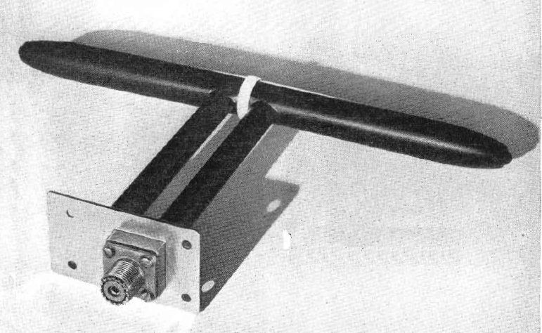
Transport aeroplanes normally carry at least two independent radio altimeters, and some types carry three. Each consists of a transceiver in the avionics bay, connected by coaxial cables to antennas in the lower fuselage. On the A320, RA 1 is shown on the captain's PFD and RA 2 on the first officer's; if one fails, both PFDs display the remaining one.
The indication appears only near the ground. On the Boeing 737 the digital readout is displayed below 2,500 ft, its box is highlighted white for 10 seconds as the aircraft descends through that height, and it turns amber below the selected radio altitude minimums. Variants with a round-dial presentation change from the digital readout to the dial below 1,000 ft.
FMCW principle
Most civil radio altimeters are frequency modulated continuous wave (FMCW) radars. They work in the 4,200 to 4,400 MHz band, which the ITU Radio Regulations reserve for radio altimeters in the aeronautical radionavigation service. The transmitter never pauses. Its frequency is swept repeatedly up and down across part of the band, usually in a triangular pattern, and the signal travels to the ground and back.
Radio waves cover roughly 1 ft per nanosecond, so each foot of height adds about 2 ns to the round trip. During that delay the transmitter has moved on to a new frequency. Mixing the outgoing signal with the returning one produces a beat frequency, the difference between the two, which is proportional to the delay and hence to height. The receiver measures that frequency and the computer converts it into feet.
Two design features follow from continuous operation:
- Separate antennas. The set transmits and receives at the same time, so it needs one antenna to transmit and another to receive, far enough apart that the strong outgoing signal does not swamp the weak echo.
- No minimum range. A pulsed radar is blind while its receiver is blanked during each transmitted pulse. An FMCW set has no such dead zone and can measure a few feet. ITU-R M.2059 also describes pulsed radio altimeters, but FMCW is the usual type on transport aeroplanes.
The antennas radiate a wide beam, so the measurement survives normal pitch and bank. The shortest echo path wins, which means the altimeter reports the nearest reflecting surface below. Some sets can measure well above 2,500 ft, but airliner displays and systems typically use radio altitude only up to 2,500 ft. Above that the indication is simply removed.
Antennas and installation delay
Radio altitude is meant to be the height of the main wheels, yet the signal leaves and returns through antennas in the fuselage belly and runs through cables to and from the avionics bay. Both add apparent height. Each installation is therefore set up with an aircraft installation delay (AID), which accounts for the cable lengths and for the height of the antennas above the lowest point of the main gear in the normal landing attitude. The altimeter then reads zero at main-wheel touchdown.
On the ground the oleos are compressed and the attitude differs from the landing attitude, so the antennas sit lower than they do at touchdown. A parked aircraft therefore usually shows a small negative radio altitude, which is normal. The same geometry explains a figure in A320 documentation: with the glideslope antenna crossing the threshold at 50 ft on a 3° path, the main gear crosses it at about 34 ft radio altitude.
What radio altitude drives
| System | Use of radio altitude | Examples |
|---|---|---|
| Minimums and callouts | Decision height alert, automatic height calls | CAT II/III DH; calls from 2,500 ft |
| Autopilot and autoland | Gain scheduling, flare, thrust retard | 737: flare about 50 ft, autothrottle retard below 27 ft |
| Fly-by-wire control laws | A320 flare mode | Pitch attitude memorised at 50 ft; from 30 ft lowered towards 2° nose-down over 8 s |
| GPWS / EGPWS | Modes 1 to 6, terrain clearance floor, geometric altitude | Basic modes about 50 to 2,450 ft |
| TCAS | Sensitivity level, RA inhibits | Descend RAs inhibited below about 1,100 ft, all RAs below about 1,000 ft, all voice below about 500 ft |
| Windshear | Arming of predictive alerts | 737: predictive alerts below 1,200 ft |
| Ground logic | Auto speedbrake and thrust reverser enabling | 737: either RA below 10 ft |
Because so much depends on it, radio altitude is monitored and compared. Automatic landing systems use two or three altimeters, and a failure or disagreement downgrades the landing capability. On the A320, if the flight guidance computers lose radio altitude data, the LOC and G/S modes and both autopilots disengage and the flight directors revert to basic modes. The fly-by-wire flare law is explained in the A320 flight control laws guide.
Automatic altitude callouts
Automatic altitude callouts, also called radio altitude callouts or automatic radio altitude callouts, are synthetic voice announcements triggered as radio altitude passes set values. On the 737 the GPWS computer generates them; on the A320 the flight warning system does. The operator chooses which calls are enabled from a menu.
- A320: "TWO THOUSAND FIVE HUNDRED" (or "TWENTY FIVE HUNDRED"), 2,000, 1,000, 500, 400, 300, 200, 100, 50, 40, 30, 20, 10 and 5 ft. There is no 150 ft call.
- Boeing 737 (most variants): 2,500, 1,000, 500, 400, 300, 200, 100, 50, 40, 30, 20 and 10 ft.
Each automatic callout has a purpose. "TWENTY FIVE HUNDRED" tells the crew that the radio altimeter has begun to track the ground. The 737 "Smart 500" option calls "FIVE HUNDRED" only when the approach is not a stable ILS or GLS, for instance on a non-precision approach, with the glideslope cancelled or with more than 2 dots of deviation. "MINIMUMS" is announced at the selected minimum, from radio altitude when the 737 MINS selector is at RADIO and from barometric altitude when it is at BARO. On the A320 an automatic "RETARD" reminds the pilot to close the thrust levers, at 20 ft on a manual landing and at 10 ft in autoland. The calls from 50 ft down give height cues in the flare without the pilot looking inside.

Radio versus barometric minimums
The choice between barometric vs radio minimums depends on the category of ILS or other approach being flown, not on crew preference. A decision altitude (DA) is referenced to mean sea level and a decision height (DH) to threshold elevation. Which instrument reads it follows from the terrain:
- Category I, approaches with vertical guidance and non-precision approaches use a barometric DA or minimum descent altitude. Radio altitude would follow every rise and dip under the approach and could trigger the decision point early or late.
- Category II (DH below 200 ft but not below 100 ft) and Category III with a DH use a DH read on the radio altimeter. Below 200 ft above the threshold, height calls on these approaches come from the radio altimeter.
For the radio altimeter to be trustworthy on these approaches, ICAO Annex 14 recommends a radio altimeter operating area before the threshold of a precision approach runway, extending at least 300 m before the threshold and 60 m either side of the extended centre line, with abrupt changes of slope avoided. Category II and III charts publish the radio altimeter height to be set, derived from the surveyed terrain.
Terminology differs. The FAA uses DA for Category I, set on the barometric altimeter, and DH for Category II and III, read on the radio altimeter. ICAO and EASA use DA/H and DH across categories, with the altimeter implied by the type of operation. In cold weather the barometric altimeter over-reads while the radio altimeter does not, so comparing the two over level terrain is a useful gross-error check (see the cold weather altimetry guide).
Failure modes and false readings
A detected failure is the benign case. The indication is replaced by a flag, dependent functions drop out, and some systems fall back to other data; the 737 autothrottle, for example, arms go-around below 2,000 ft radio altitude, or below 15,500 ft pressure altitude if both radio altimeters have failed.
The dangerous case is a wrong reading that still looks valid. Faulty antennas or cables, moisture and interference can make an altimeter jump to a small or negative value at height. Whatever uses that value then acts on it.
On 25 February 2009 Turkish Airlines flight TK1951, a Boeing 737-800, was approaching runway 18R at Amsterdam Schiphol. The crew intercepted the localiser only 5.5 NM from the runway, above the glideslope, and had to descend from 2,000 ft to capture it, which kept them busy. The left radio altimeter began to indicate -8 ft. On the 737 the autothrottle always took its height from the left radio altimeter, a design point not described in the training material available to pilots, and because the erroneous value was below 27 ft and the other conditions were met, it entered its RETARD flare mode and closed the thrust levers. The autopilot, unaffected, kept following the glideslope by raising the nose as speed decayed. The crew did not notice the lack of thrust until the aircraft neared the stall, and the recovery came too late. The aircraft crashed short of the runway; nine of the 135 occupants died, including all three pilots.
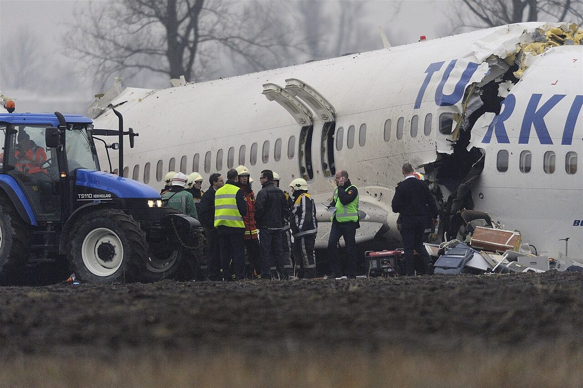
The Dutch Safety Board highlighted the single-source design, the compressed approach and the crew's monitoring of speed and thrust. The lessons apply to any type: read the flight mode annunciator after every change, keep speed and thrust in the scan on a coupled approach, and compare the two radio altimeters when anything behaves oddly.
5G C-band interference
Many radio altimeters were designed when the neighbouring spectrum was quiet, and their receivers can respond to strong signals just outside 4.2 to 4.4 GHz. Such interference could degrade or falsify radio altitude exactly where it matters most, close to the ground.
In the United States, 5G networks were licensed in the C-band between 3.7 and 3.98 GHz, 220 MHz below the altimeter band. The FAA's AD 2021-23-12, issued in December 2021, required flight manual limitations prohibiting certain operations that need radio altimeter data in the presence of 5G interference identified by NOTAM. The FAA then approved alternative methods of compliance for altimeter models shown to be tolerant. In 2022 the FAA and the two main network providers, Verizon and AT&T, agreed that the providers would keep mitigations around airports until 1 July 2023 while airlines retrofitted filters or replaced altimeters. A superseding AD published in May 2023 required 5G C-band-tolerant radio altimeters or approved filters for airline operations in the contiguous United States by 1 February 2024.
Europe's 5G C-band sits lower, at 3.4 to 3.8 GHz, leaving 400 MHz of separation. EASA did not adopt the FAA directives. It issued Safety Information Bulletin 2021-16 in December 2021, which noted that no unsafe interference had been identified in Europe but asked operators and crews to stay aware of the issue and to report radio altimeter anomalies.
Exam tip: radio altimeter questions test FMCW in 4,200 to 4,400 MHz, the beat frequency proportional to height, separate transmit and receive antennas, a range of 0 to 2,500 ft, zero at main-wheel touchdown through the installation delay, and DH on the radio altimeter for CAT II and III but not CAT I.
Frequently asked questions
How does a radio altimeter work?
It transmits a continuous signal towards the ground while sweeping its frequency up and down within the 4.2 to 4.4 GHz band. By the time the echo returns, the transmitter has moved to a different frequency, so mixing the two produces a beat frequency proportional to the round-trip time and therefore to height. Because it transmits and receives at the same time, it needs separate transmit and receive antennas under the fuselage.
What is the difference between a radio altimeter and a barometric altimeter?
A barometric altimeter converts static pressure into altitude above a pressure datum such as QNH or 1013 hPa, and is the reference for flight levels, altitudes and terrain clearance. A radio altimeter measures the actual height of the wheels above whatever lies directly underneath, so it follows every hill, building and valley. It is precise close to the ground but on most airliners reads only below 2,500 ft.
Why can 5G interfere with radio altimeters?
Radio altimeters use 4.2 to 4.4 GHz, and many older receivers also respond to strong signals just outside that band. In the United States, 5G C-band networks transmit between 3.7 and 3.98 GHz, only 220 MHz below it. The FAA restricted radio-altitude-dependent operations in affected areas from late 2021 and then required tolerant altimeters or filters for airline operations in the contiguous United States by 1 February 2024. EASA issued a Safety Information Bulletin instead.
Why does the radio altimeter show a negative height on the ground?
The installation is calibrated through the aircraft installation delay so that it reads zero when the main wheels touch the runway in the landing attitude, although the antennas are then still some feet above the surface. Parked, with the oleos compressed and the fuselage in a different attitude, the antennas sit lower than at touchdown, so a reading a few feet below zero is normal.
When are radio minimums used instead of barometric minimums?
Category II and III approaches use a decision height read on the radio altimeter, because it is precise low down and the terrain before the threshold is surveyed. Category I, approaches with vertical guidance and non-precision approaches use a barometric decision altitude or minimum descent altitude, because radio altitude would follow uneven ground under the approach. On the Boeing 737 the crew sets the MINS selector to RADIO or BARO accordingly.
Test yourself on Radio Altimeter
The v1prep banks cover this topic in Instrumentation (022), with a worked explanation for every answer. EASA ATPL, PPL, IR and CPL, the FAA written tests and A320/B737 type ratings.
Start practising →Sources and further reading
- ITU-R Recommendation M.2059, Operational and technical characteristics of radio altimeters in the band 4 200-4 400 MHz
- Dutch Safety Board, Turkish Airlines, crashed during approach, Boeing 737-800, Amsterdam Schiphol Airport
- Flight Safety Foundation, Automation at Odds (TK1951)
- FAA, 5G and Aviation Safety
- Federal Register, Airworthiness Directives; Transport and Commuter Category Airplanes (5G C-band, May 2023)
- EASA Safety Information Bulletin 2021-16, 5G mobile telecommunications systems and radio altimeters
Library articles are written for study and exam preparation. They do not replace your aircraft's approved documentation, your operator's procedures or the regulations themselves.