B737 Autopilot Flight Director System
The autopilot flight director system (AFDS) of the Boeing 737 is a dual system of two flight control computers and a single mode control panel. It gives flight director guidance and autopilot control in pitch and roll from take-off to a dual-channel automatic landing or go-around.
The Boeing 737's automatic flight system consists of the autopilot flight director system (AFDS) and the autothrottle. The AFDS is a dual system of two flight control computers (FCCs) and a single mode control panel (MCP). For autopilot operation each FCC drives its own pitch and roll hydraulic servos, which move the flight controls through two separate hydraulic systems. The flight management computer (FMC) supplies the LNAV and VNAV guidance, and the flight directors show each pilot the commands.
This article follows the 737 NG flight crew operations manual (FCOM), which calls the computers FCCs, and notes where the MAX differs. The principles are in autopilot, flight director and autoflight modes and autoland; thrust is covered in B737 autothrottle and thrust management.

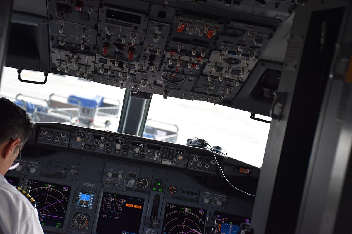
Mode control panel and annunciations
The MCP is the pilot flying's responsibility; flying by hand, the pilot flying asks the pilot monitoring to make the changes, and every value set is checked on the flight instruments. Its main controls:
| Control | Range and behaviour |
|---|---|
| IAS/MACH display | 100 kt at power-up; 100 kt to VMO and .60M to MMO; blank in VNAV, with the autothrottle in FMC SPD and in a two-engine AFDS go-around |
| C/O switch | Switches the display between IAS and Mach; automatic changeover at about FL260 |
| Bank angle selector | 10, 15, 20, 25 or 30° |
| ALTITUDE display | 0 to 50,000 ft in 100 ft steps |
| VERT SPEED display | -7,900 to +6,000 fpm, in 50 fpm steps below 1,000 fpm and 100 fpm above |
A flashing character in the IAS/MACH window is the overspeed limiting symbol (VMO/MMO, gear or flap limit); the underspeed limiting symbol appears at minimum speed. A master (MA) light by each F/D switch shows which FCC controls the flight director modes; with an autopilot in CMD, the FCC of the first autopilot engaged is master. Both MA lights on mean independent flight director operation, each FCC driving its own side, which occurs with neither autopilot in CMD and both F/Ds on, in APP after LOC and G/S capture, or in TO or GA below 400 ft RA.
The flight mode annunciations show the autothrottle mode, the roll and pitch modes and the AFDS status. A rectangle, the mode change highlight, is drawn round each newly engaged mode for 10 seconds, and flashes when a CWS mode engages. After IRS alignment the three mode fields are blank and the status reads FD. Calling out each change is good crew practice.
CMD, CWS and disengagement
Each autopilot has two engage switches. CMD engages it to fly the selected modes; CWS, control wheel steering, is described in the ATPL texts as manoeuvring through the autopilot with pressure on the control wheel; it is annunciated as amber CWS R and CWS P. Engagement in either is inhibited unless no force is applied to the control wheel and the STAB TRIM AUTOPILOT cutout switch is at NORMAL. With the flight director on and the autopilot off or in CWS, the status is FD.
Only one autopilot can be engaged at a time, except in APP mode: outside it, engaging the second disengages the first. The limitations forbid engaging the autopilot below 400 ft AGL after take-off and using aileron trim with it engaged.
The autopilot disengages when:
- either A/P disengage switch is pushed (both autopilots disengage, the lights flash and the warning tone sounds for at least 2 seconds);
- the A/P DISENGAGE bar is pulled down, exposing a yellow background and preventing re-engagement;
- a control wheel trim switch is used, or the STAB TRIM AUTOPILOT cutout switch goes to CUTOUT;
- the pilot overrides on the column or wheel, or pushes an illuminated engage switch;
- TO/GA is pushed below 2,000 ft RA without FLARE armed;
- the stick shaker persists for more than five seconds.
The A/P disengage lights turn steady red when the stabiliser is out of trim below 800 ft RA on a dual-channel approach, or when ALT ACQ is inhibited in an autopilot go-around because the trim does not suit single-autopilot flight. The amber STAB OUT OF TRIM light means an engaged autopilot is not trimming properly.
Lateral modes
- HDG SEL first turns the shorter way to the selected heading, then follows the selector's direction of rotation, at the bank angle selected.
- LNAV arms on the ground with the origin runway and an active route in the FMC, the first leg within 5° of runway heading and both F/D switches ON; guidance starts at 50 ft. In flight it engages within 3 NM of the route on any heading, or further out on an intercept of 90° or less that meets the leg before the active waypoint. It disconnects at the end of the route, at a discontinuity, on HDG SEL or on capture of a VOR/LOC course.
- VOR/LOC captures the localiser no later than half a dot. With a localiser frequency tuned, the NAV receivers switch from the tail to the nose antenna when VOR/LOC arms or engages; if they do not, LOC is inhibited. Back-course tracking is not available.
Pitch modes and LVL CHG
On the ground, F/D switches ON arm TO/GA. Pushed for take-off, it commands 10° nose down until 60 kt, then 15° nose up, held after lift-off until the climb rate is sufficient, then MCP speed (normally V2) plus 20 kt. After an engine failure the target becomes V2 if speed is below V2, the existing speed between V2 and V2 + 20, and V2 + 20 above that. Below 400 ft RA only both F/D switches OFF end the take-off mode.
LVL CHG pairs the elevator with speed: in a climb the autothrottle holds limit thrust and the AFDS the selected speed; in a descent the autothrottle sets idle. It is inhibited after glideslope capture and, by the limitations, not used on final below 1,000 ft above field elevation. ALT HOLD holds the MCP altitude, or the uncorrected barometric altitude at which ALT HLD was pressed; a later altimeter setting change does not move it. V/S arms when a new MCP altitude more than 100 ft away is set while holding at the MCP altitude. ALT ACQ is the capture phase as the aeroplane approaches the MCP altitude, and with it the autothrottle engages in speed mode. ALT HOLD, V/S and LVL CHG are all inhibited after glideslope capture.
VNAV modes and intervention
VNAV arms on the ground with a valid flight plan, performance data entered and executed and both F/D switches ON, and becomes active at 400 ft AGL; it is inhibited below 400 ft RA or without performance initialisation. The FMC divides the work:
| Phase | Autothrottle | AFDS pitch |
|---|---|---|
| Climb | FMC thrust limit (N1) | FMC target speed |
| Cruise | FMC target speed (FMC SPD) | FMC altitude |
| Path descent (VNAV PTH) | Idle; FMC SPD if ground speed is too low to hold the path | FMC vertical path |
| Speed descent (VNAV SPD) | Idle | Target descent speed |
SPD INTV opens the IAS/MACH window so the crew can set the speed; blanking it again restores the FMC target. A speed intervention in a late path descent changes VNAV PTH to VNAV SPD until the path is regained. ALT INTV deletes the lowest altitude constraint below the MCP altitude in a climb and the highest above it in a descent, and in cruise starts a cruise climb to an MCP altitude set higher. VNAV ends with another pitch mode, glideslope capture or the end of the LNAV route. Descent planning is in B737 FMC and CDU.
Speed limiting and mode reversions
Command speed limiting keeps speed, pitch and thrust commands within VMO/MMO, the flap and gear placards and minimum speed. Speeds above VMO/MMO cannot be selected; placard-exceeding or below-minimum speeds can be, and the system then flies to just short of the limit. Minimum speed, about 1.3 Vs for the flap setting, comes from the angle of attack vanes.
- Placard limit reversion: with the AFDS engaged but not controlling speed, an armed autothrottle reverts to SPEED and holds just below the placard. For VMO/MMO, with the autothrottle in a speed mode at idle, V/S changes to LVL CHG. Without the autothrottle there is no gear or flap reversion; the AFDS limits VMO/MMO itself.
- Minimum speed reversion: at or just below minimum speed, V/S reverts to LVL CHG and the AFS commands minimum speed plus 5 kt. VNAV or V/S do not revert with the flaps beyond 12.5, and there is no reversion with the autothrottle off in ALT HOLD or after glideslope capture, or on a VNAV PTH level segment. In a LVL CHG climb at minimum speed that cannot hold a minimum climb rate, the autopilot disengages and the F/D bars retract.
Warning: on an ILS approach the autopilot and flight director hold the glideslope in windshear without regard to angle of attack or stick shaker. The crew must intervene with TO/GA or by flying manually.
Approach modes and IAN
The APP switch arms localiser and glideslope capture and enables engagement of both autopilots. The localiser must be captured before the glideslope, which is captured at 2/5 dot below. After capture, APP is left by TO/GA, by disengaging the autopilots and switching both F/Ds off, or by retuning a NAV receiver. With a radio altimeter inoperative, the autopilot disengages 2 seconds after LOC and G/S capture. The flight director has no flare: its bars retract at about 50 ft RA.
On aircraft with integrated approach navigation (IAN), FMC approaches give glide path (G/P) and FAC deviations and alerts displayed like an ILS. IAN is used only for approaches with a published GP angle on the LEGS page, a runway waypoint or a missed approach point before the runway, never with QFE, and an alert sounds if the autopilot is still engaged below 100 ft RA in FAC or G/P.
Dual-channel approach and autoland
A dual-channel approach needs both NAV receivers on the ILS, both autopilots in CMD by 800 ft RA and two generators powering the buses. Approaching the ground:
| Height (RA) | Event |
|---|---|
| Below 1,500 ft | Second autopilot couples; ILS deviation monitor tested; FLARE armed; SINGLE CH out; autopilot go-around armed |
| 800 ft | Last moment to engage the second autopilot |
| 400 ft | Stabiliser trimmed further nose up |
| About 350 ft | Both autopilots disengage if FLARE is not armed |
| About 50 ft | Flare begins |
| About 27 ft | Autothrottle retards (RETARD), reaching idle at touchdown |
With one autopilot, SINGLE CH stays amber for the whole approach and there is no automatic flare, touchdown or go-around; the autopilot is off no later than the minimum use height (50 ft AGL under FAA rules). After an autoland the autopilot is disengaged after touchdown. The red AUTOLAND warning light, armed below 500 ft, flashes if an autopilot disengages, a stabiliser trim warning occurs or an ILS deviation occurs below 200 ft. Autoland is limited to glideslopes of 2.5 to 3.25° and, on most variants, flaps 30 or 40 with both engines operating.
On fail-operational aircraft, the autoland status annunciation is shown on the outboard display units and checked at 500 ft above field elevation. A failure above alert height gives amber NO LAND 3, when a safe landing is still possible and LAND 2 becomes the status, or NO AUTOLAND, when it is not.
Automatic go-around
An autopilot go-around needs dual-channel operation and arms with FLARE armed. The autothrottle go-around mode arms below 2,000 ft RA. A first TO/GA push engages it in GA, towards a reduced go-around N1 giving 1,000 to 2,000 fpm, and a second push gives full go-around N1. The AFDS holds the ground track and commands 15° nose up, then the target speed for the flap setting. Below 400 ft RA it stays in go-around unless both autopilots and F/Ds are disengaged; FMC go-around logic is described in B737 FMC and CDU.
Differences on the 737 MAX
The FSB lists no change to the MCP, finds the NG and MAX autoland systems identical, with differences training only between fail-passive and fail-operational systems, and grades the updated AFDS logic Level B. Since the return to service:
- in pitch modes without speed protection, the MAX autopilot disconnects 1 second after stick shaker onset and the F/D bars bias out of view, except in dual-channel operation;
- a cross-FCC trim monitor can disconnect the autopilot on a failed side, which then cannot be re-engaged there;
- under the revised FAA master minimum equipment list, both FCCs are required for passenger dispatch;
- EASA's AFM bases the autopilot minimum use height on a 1-second recognition time.
Frequently asked questions
What is the difference between CMD and CWS on the Boeing 737?
Both engage the same autopilot. In CMD the autopilot flies the modes selected on the mode control panel or by the FMC. In CWS, control wheel steering, the ATPL texts describe the pilot manoeuvring through the autopilot with pressure on the control wheel, and the flight mode annunciator shows CWS P and CWS R in amber. Engagement in either is inhibited unless no force is applied to the wheel and the STAB TRIM AUTOPILOT cutout switch is at NORMAL.
When must the second autopilot be engaged for a dual-channel approach on the 737?
By 800 ft radio altitude, with both VHF NAV receivers tuned to the ILS and APP mode selected; below 800 ft engagement of the second autopilot is inhibited. Below 1,500 ft, after localiser and glideslope capture, it couples to the controls, the ILS deviation monitor is tested, FLARE armed appears and SINGLE CH goes out. Dual-channel operation also needs two generators powering the buses.
What does SINGLE CH mean on the 737 flight mode annunciator?
It is an amber autopilot status annunciation shown on an ILS approach after localiser capture with one autopilot. On a single-autopilot approach it stays for the whole approach; automatic flare, touchdown and autopilot go-around are then not available, and the autopilot must be off by the minimum use height. On a dual-autopilot approach it goes out once the second autopilot has coupled and passed the pitch monitor confidence test.
What is minimum speed reversion on the 737 AFDS?
If speed falls to or slightly below the minimum speed, about 1.3 Vs for the flap setting, an underspeed symbol appears in the IAS/MACH window and, in V/S, the AFDS reverts to LVL CHG, commanding minimum speed plus 5 kt. There is no reversion from VNAV or V/S with the flaps beyond 12.5, nor with the autothrottle off in ALT HOLD or after glideslope capture, nor on a VNAV PTH level segment.
How does an automatic go-around work on the Boeing 737?
It needs both autopilots engaged and arms when FLARE armed is annunciated. A first TO/GA push below 2,000 ft radio altitude engages the autothrottle in GA towards a reduced go-around N1 giving 1,000 to 2,000 fpm, while the AFDS pitches up and holds the ground track; a second push gives full go-around thrust. If the stabiliser trim does not suit single-autopilot flight, ALT ACQ is inhibited and the A/P disengage lights show steady red.
Why does the 737 MAX autopilot disconnect when the stick shaker starts?
Since the return-to-service software, in pitch modes without speed protection, except flare, the autopilot disconnects one second after stick shaker onset and the flight director bars bias out of view. Guidance returns at the top of the amber band, or earlier when a mode with speed protection is selected; a previous ALT HLD then comes back as LVL CHG. This does not apply in dual-channel operation. On the NG the autopilot disengages if the shaker lasts more than five seconds.
Test yourself on B737 Autopilot Flight Director System
The v1prep banks cover this topic in the B737 type-rating bank, with a worked explanation for every answer. EASA ATPL, PPL, IR and CPL, the FAA written tests and A320/B737 type ratings.
Start practising →Sources and further reading
- FAA Flight Standardization Board Report, Boeing 737
- FAA, Summary of the FAA's Review of the Boeing 737 MAX (November 2020)
- EASA, Boeing 737 MAX Return to Service Report (January 2021)
- EASA Easy Access Rules for Large Aeroplanes (CS-25), CS 25.1329 and AMC 25.1329, Flight guidance system
- EASA, Easy Access Rules for All Weather Operations (CS-AWO)
- EASA, Explanatory Note to ED Decision 2018/001/R, Part-FCL theoretical knowledge learning objectives (022 Instrumentation)
Library articles are written for study and exam preparation. They do not replace your aircraft's approved documentation, your operator's procedures or the regulations themselves.