Radio Wave Propagation
Radio wave propagation is the way a radio signal travels from transmitter to receiver: along the Earth's surface, refracted back to Earth by the ionosphere, or in a straight line through the lower atmosphere. Which path it takes depends mainly on its frequency, and it weakens with distance through spreading and absorption.
A radio wave leaving an antenna can reach a distant receiver by three routes. At low frequencies it clings to the Earth's surface and follows its curvature. At high frequencies it climbs to the ionosphere and is refracted back down, hundreds or thousands of miles away. Above about 30 MHz it does neither and travels in a straight line, stopping at the horizon. Radio wave propagation is the study of these paths, and frequency decides which one a signal takes.
Propagation explains the range and the quirks of every radio aid and radio: why an NDB can be received at low level beyond the horizon but wanders at night, why VHF fades out behind a hill, why HF crews change frequency at dusk, and why a distant station sometimes breaks through on a local frequency. The waves themselves are described in radio waves, modulation and antennas.
Attenuation and the inverse-square law
Every signal weakens with distance, a loss called attenuation. It has two causes:
- Absorption: energy is lost to the air, water vapour, dust, the Earth's surface and the ionosphere. It increases with frequency, especially above about 1 GHz. Rain attenuates wavelengths shorter than about 4 cm significantly, and snow and heavy rain affect the UHF glide path more than the VHF localiser.
- Spreading: the energy spreads over an ever larger sphere, so its power per unit area falls with the square of the distance, the inverse-square law.
Because of the inverse-square law, doubling the range of a transmitter needs four times the power. A primary radar suffers the loss twice, out and back, so doubling its range takes sixteen times the power. An NDB's surface-wave range grows only with the square root of its power.
Surface (ground) waves
The surface wave, or ground wave, is guided along the Earth's surface and bends around its curvature by diffraction. Its attenuation climbs steeply with frequency, so it gives useful range in the VLF, LF and MF bands and is negligible at VHF and above; of any set of frequencies, the lowest gives the greatest surface-wave range.
The surface also matters. Sea water is a good electrical conductor, so attenuation is lower and range greater over the sea than over land. Vertical polarisation is used at LF and MF to make the most of the surface wave. ATPL texts estimate NDB range as about 3√P NM over the sea and 2√P NM over land, with P the power in watts: a 1 kW beacon reaches roughly 95 NM over the sea and 63 NM over land.
Crossing a coastline, the surface wave speeds up over the sea and bends, so bearings taken over water from an inland beacon are displaced: coastal refraction, covered with the other ADF errors in NDB and ADF.
The ionosphere and its layers
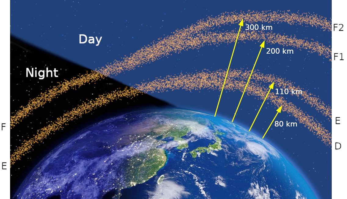
The ionosphere is the part of the upper atmosphere in which solar radiation strips electrons from gas molecules. Ionisation builds from sunrise, peaks shortly after local midday, around 1400, and is lowest just before dawn. It is stronger in summer than in winter and at low latitudes than at high ones.
| Layer | Mean height | Behaviour |
|---|---|---|
| D layer | About 75 km | Forms at sunrise, disappears at sunset; by day it absorbs LF and MF energy |
| E layer | About 125 km | Returns LF and MF sky waves at night; the source of sporadic-E |
| F layer | About 225 km | Splits into F1 and F2 by day; gives the longest single-hop sky-wave range |
The D layer is the key to ADF night effect. By day it absorbs the sky wave of an NDB, so only the surface wave reaches the aircraft. After dark it disappears, sky waves return from the E layer and arrive with random phase and polarisation, and the signal fades while the needle wanders. The effect is worst at dusk and dawn and at long range, which is why an NDB's designated operational coverage (DOC) applies by day only. The FAA's AIM likewise warns that at night radio beacons are vulnerable to interference from distant stations.
Sky waves, critical angle and skip distance
A sky wave is a wave refracted back to Earth by the ionosphere. How much it bends depends on the density of ionisation and on the frequency: the higher the frequency, the less it bends. For each frequency there is a critical angle of incidence at the ionosphere. A wave that meets the layer more steeply than that passes through into space; one that meets it more obliquely is returned to Earth.
The ray at the critical angle comes down at the skip distance, the shortest distance from the transmitter at which a sky wave is received. Beyond the end of the surface wave and short of the skip distance lies the dead space (skip zone), where nothing is received.
| Change | Critical angle | Skip distance | Dead space |
|---|---|---|---|
| Higher frequency | Larger | Longer | Larger (the surface wave also shrinks) |
| More ionisation (by day) | Smaller | Shorter | Smaller |
A single hop from the E layer reaches at most about 1,350 NM, and from the F layer about 2,200 NM; greater ranges need several hops between ionosphere and Earth.
The maximum usable frequency (MUF) is the highest frequency that the ionosphere will return over a given path. It gives the path with the least attenuation, but the signal is lost if the ionisation falls, so HF operators work at the optimum working frequency, about 0.85 × MUF. At night ionisation falls and, for the same range, a frequency of roughly half the day frequency is needed. The rule is higher frequencies by day and lower by night, which is why oceanic HF frequencies are assigned in families with day and night choices (see VHF, HF and satellite communications).
Above about 30 MHz, refraction is too weak to return the wave, which passes through the ionosphere. It is still slowed: for a single-frequency GNSS receiver, ionospheric delay is the largest single source of error (see GNSS).
Space waves and line-of-sight range
At VHF and above, the only normal path is the space wave: the direct wave from aerial to aerial plus the wave reflected from the ground. Range is therefore limited by line-of-sight propagation. Refraction in the lower atmosphere bends the waves slightly downwards, putting the radio line-of-sight range about 15% beyond the geometric horizon: roughly 1.23√h NM against 1.06√h NM.
The VHF range formula gives the maximum theoretical range between two aerials:
Range (NM) = 1.23 × (√h₁ + √h₂), with h₁ and h₂ the heights of the two aerials in feet above mean sea level.
| Station aerial | Aircraft | Maximum theoretical range |
|---|---|---|
| 196 ft | 2,500 ft | 1.23 × (14 + 50) ≈ 79 NM |
| 400 ft | 25,000 ft | 1.23 × (20 + 158) ≈ 220 NM |
| 900 ft | FL360 | 1.23 × (30 + 190) ≈ 270 NM |
| Sea level | 10,000 ft | 1.23 × (0 + 100) ≈ 123 NM |
The VHF line-of-sight range is why VHF voice at FL300 reaches only about 200 NM, and why oceanic flights need HF or satellite links. Doubling the aircraft's height multiplies its share of the range by only about 1.4. The formula can also be turned round: a radar aerial at 1,700 ft can detect an aircraft at 200 NM only if it is at about 15,000 ft or higher.
Terrain between the aerials blocks the signal completely, so a station 40 NM away may be unreadable from a valley at 1,500 ft and clear after a climb. The FAA's AIM notes that VORs are subject to line-of-sight restrictions, with range varying with the altitude of the receiver, and that its standard service volumes do not account for blockage by terrain. The limit is also useful: stations out of each other's sight can share a frequency. France, for example, notifies ICAO that it separates VHF assignments geographically by the radio horizon, except for broadcast services on 25 kHz channels.
Exam tip: use feet, not metres, and add the square roots, not the heights. For 196 ft and 2,500 ft, 1.23 × √(196 + 2,500) gives 64 NM instead of the correct 79 NM.

Super-refraction and ducting
Normal refraction assumes a standard atmosphere. When humidity decreases with height and temperature falls more slowly than standard or increases through an inversion, the waves bend down more sharply: super-refraction. It is favoured by high pressure and fine weather and by warm air over a cool surface, and can extend VHF and higher ranges by around 40%.
In the extreme case the waves bend down faster than the Earth curves away and are trapped in a shallow layer: radio ducting. A duct needs a temperature inversion together with a rapid decrease of humidity with height, and forms most often over land at night and in the early morning under high pressure, or where warm air lies over a cold sea. Signals then travel hundreds of miles beyond the horizon, stations sharing a frequency interfere, and ground radar can show false ranges. Ducting is commonest in the UHF and SHF bands; at VHF it needs a duct about 500 ft deep.
Sporadic-E, fading and multipath
Sporadic-E, or scatter propagation, comes from patches of unusually dense ionisation in the E layer, which scatter weak VHF sky waves forward at random. It is unpredictable and useless for communication, but it can let a distant VHF aid interfere with one sharing its frequency, since VHF frequency protection relies on line of sight.
Radio fading is a rise and fall of signal strength caused by waves arriving by two paths with changing phase, reinforcing and then cancelling each other: the direct and ground-reflected components of the space wave, or the surface and sky waves of an NDB at night. HF sky-wave reception is also prone to fading. Static adds noise: thunderstorms radiate strongly at LF and MF, and precipitation static from charged airframes, reduced by static dischargers, affects HF and ADF reception in particular.
Multipath interference occurs when reflections from terrain, buildings or the aircraft itself reach the receiver alongside the direct signal. It causes VOR scalloping and course bends, which a Doppler VOR resists much better than a conventional one (see VOR), and range errors in GNSS, reduced by mounting the antenna on top of the fuselage and ignoring satellites less than about 5° above the horizon. Reflections from vehicles and aircraft near the antennas are also why the ILS has protected critical and sensitive areas (see instrument landing system).
| Band | Main path | Typical range | Main disturbances |
|---|---|---|---|
| LF/MF | Surface wave (sky wave at night) | Tens to hundreds of NM | Night effect, coastal refraction, static |
| HF | Sky wave | Thousands of NM | Skip, dead space, day-night changes, fading |
| VHF and above | Space wave | Line of sight | Terrain, ducting, sporadic-E, multipath |
Frequently asked questions
What is the VHF range formula?
The maximum theoretical VHF range in nautical miles is 1.23 times the sum of the square roots of the two antenna heights in feet above mean sea level. A station aerial at 196 ft and an aircraft at 2,500 ft give 1.23 times 14 plus 50, about 79 NM. With the station aerial at sea level its term drops out, so an aircraft at 10,000 ft has a range of 1.23 times 100, about 123 NM.
Why can VHF not be received beyond the horizon?
Above about 30 MHz there is no usable surface wave and the ionosphere does not return the signal, so the only normal path is the space wave, a direct line from aerial to aerial plus a ground reflection. Range is therefore limited to line of sight, extended only slightly by refraction in the lower atmosphere, and terrain in between blocks the signal completely. Climbing is the usual cure.
What is skip distance in HF radio?
Skip distance is the distance from the transmitter to the nearest point at which the first sky wave returns from the ionosphere. Nearer than that, sky waves have either passed through the ionosphere or not yet come down. The gap between the end of the surface wave and the first sky wave is the dead space, where nothing is received. Higher frequencies increase both the skip distance and the dead space.
Why does an HF frequency that works by day fail at night?
The ionosphere is ionised by solar radiation, and its ionisation falls after sunset. The highest frequency it can return drops, so a daytime frequency may simply pass through into space at night. For the same range a lower frequency, roughly half the day frequency, is needed. Oceanic HF frequencies therefore come in families with day and night choices, and crews change frequency around dawn and dusk.
What is radio ducting?
Ducting, or super-refraction, happens when a temperature inversion combines with a rapid decrease of humidity with height. Radio waves are bent downwards more than normal and trapped in a shallow layer, reaching hundreds of miles beyond the horizon. It is commonest in the UHF and SHF bands and occurs at VHF only in a deep duct. It can cause interference between stations sharing a frequency and false ranges on ground radar.
Test yourself on Radio Wave Propagation
The v1prep banks cover this topic in General and Radio Navigation (061/062), with a worked explanation for every answer. EASA ATPL, PPL, IR and CPL, the FAA written tests and A320/B737 type ratings.
Start practising →Sources and further reading
- EASA, Explanatory Note to ED Decision 2018/001/R, Part-FCL theoretical knowledge learning objectives (062 Radio Navigation, 090 Communications)
- FAA Instrument Flying Handbook (FAA-H-8083-15B), Chapter 9, Navigation Systems (basic radio principles)
- FAA Aeronautical Information Manual, Chapter 1 Section 1 (1-1-2 NDB, 1-1-3 VOR, 1-1-7 DME, 1-1-8 NAVAID service volumes)
- ICAO Annex 10, Aeronautical Telecommunications, Volume I, Radio Navigation Aids (copy published by IACM Mozambique)
- AIP France, GEN 1.7, Differences from ICAO Standards, Recommended Practices and Procedures (Annex 10, Volume V)
- SKYbrary, Non-Directional Beacon (NDB)
Library articles are written for study and exam preparation. They do not replace your aircraft's approved documentation, your operator's procedures or the regulations themselves.