Radar Principles
Radar (radio detection and ranging) locates objects by transmitting radio energy and receiving what they reflect. A primary radar measures range from the time an echo takes to return, bearing from the direction its antenna is pointing and, through the Doppler effect, how fast a target is closing or receding.
Radar, from radio detection and ranging, locates objects by the energy they send back. A primary radar transmits a pulse, listens for the echo and times it: the delay gives the range, the direction in which the antenna was pointing gives the bearing, and a change in frequency, the Doppler shift, reveals movement towards or away from the antenna. The target needs no equipment of its own, the method's strength and its weakness.
The same physics serves ATC surveillance and surface radars, precision approach radar, the aircraft's own weather radar and radio altimeter, and the Doppler navigator that preceded inertial and satellite navigation.
- Primary, secondary and continuous-wave radar
- The radar mile
- Pulse repetition frequency and maximum range
- Pulse width, resolution and minimum range
- Antennas and the searchlight principle
- Displays and moving target indication
- Reflection, second-trace returns and masking
- Surveillance and surface movement radars
- Doppler effect and Doppler navigation
- Frequently asked questions
Primary, secondary and continuous-wave radar
A primary radar sees the aircraft's skin. It works whether or not the transponder does, but it also paints weather, terrain, buildings and birds, cannot tell one aircraft from another and gives no height. The energy travels out and back, spreading in both directions, so the returned power falls with the fourth power of range: doubling the range of a primary radar needs 16 times the transmitter power. A secondary surveillance radar interrogates a transponder, which replies on another frequency. Each leg is one-way, so far less power is needed, and the reply carries identity and pressure altitude (see transponder and SSR).
A pulse radar transmits short bursts and listens in the silent interval between them. A continuous-wave (CW) radar transmits without a break, so it has no minimum range, but an unmodulated continuous signal carries no timing mark: it measures the Doppler shift of a moving target, not its range. To measure distance the frequency must be varied. The radio altimeter sweeps its carrier up and down (frequency-modulated continuous wave, FMCW) and converts the difference between the frequency leaving and the one returning into height. Doppler navigation radars have also used continuous-wave transmission.
Radars work at VHF and above, where static and ionospheric effects are negligible and short wavelengths give narrow beams from antennas of practical size. The wavelength also decides what the radar sees. Below about 4 cm, attenuation by rain becomes significant, so long-range surveillance radars use wavelengths of 10 cm or more, which pass through precipitation and return few weather echoes. Airborne weather radar and precision approach radar work at about 3 cm, which large raindrops reflect well. Circular polarisation helps a surveillance radar ignore rain: a spherical drop reverses the sense of rotation of the reflected wave, so the receiver rejects it, while an aircraft still returns a usable echo.
The radar mile
Radio energy travels at about 300,000 km/s and covers a nautical mile in about 6.18 µs. An echo from a target 1 NM away therefore returns after 12.36 µs, a figure known as the radar mile. Range follows directly from the echo delay:
- range in NM = delay in µs ÷ 12.36
- range in km = delay in µs × 0.15
An echo returning 900 µs after transmission comes from about 73 NM; one returning after 1,720 µs comes from about 139 NM, or 258 km.
Range is also limited by the horizon. The usual approximation for line-of-sight range in nautical miles is 1.23 × (√h₁ + √h₂), with both heights in feet. A radar head at 1,700 ft can see an aircraft 200 NM away only if the aircraft is at about 15,000 ft or higher.
Pulse repetition frequency and maximum range
The pulse repetition frequency (PRF) is the number of pulses transmitted per second (pps). Its reciprocal is the pulse repetition interval (PRI), the time from the start of one pulse to the start of the next. Each echo must return before the next pulse leaves, or the receiver cannot tell which pulse it belongs to, so the PRI sets the maximum unambiguous range:
- maximum range in NM = PRI in µs ÷ 12.36, or about 81,000 ÷ PRF
- maximum PRF = 81,000 ÷ required range in NM
| PRF | PRI | Maximum unambiguous range |
|---|---|---|
| 275 pps | 3,636 µs (3.64 ms) | About 294 NM |
| 405 pps | 2,469 µs | About 200 NM |
| 450 pps | 2,222 µs | About 180 NM |
| 500 pps | 2,000 µs | About 162 NM |
| 810 pps | 1,235 µs | About 100 NM |
| 10,000 pps | 100 µs | About 8 NM |
A low PRF gives long range, a high PRF short range. The PRF only sets the range at which echoes can be timed without ambiguity; power, antenna gain, target size and the horizon decide whether a target within it is detected.
Pulse width, resolution and minimum range
The pulse width, or pulse length, is the duration of each pulse. In space, each microsecond of pulse is 300 m long. While a pulse is being transmitted the receiver is blanked, so the radar cannot see anything whose echo would come back before the pulse has ended: the minimum range is half the pulse length, 150 m for every microsecond of pulse width.
Radar resolution is the ability to show two targets as two. Range resolution depends on pulse width: two targets on the same bearing that are closer together than half the pulse length return overlapping echoes and appear as one. Bearing resolution depends on beam width: two targets at the same range within one beam width merge. The width of the beam in distance grows with range; by the 1 in 60 rule, a 1° beam is about 1 NM wide at 60 NM. Short pulses and narrow beams improve resolution, and both are easier at higher frequencies. Long pulses carry more energy, and so more range, which is why long-range radars accept poorer resolution.
Antennas and the searchlight principle
A primary radar finds bearing by the searchlight principle: a narrow beam sweeps round, and the direction in which the antenna points when an echo arrives is the target's bearing.
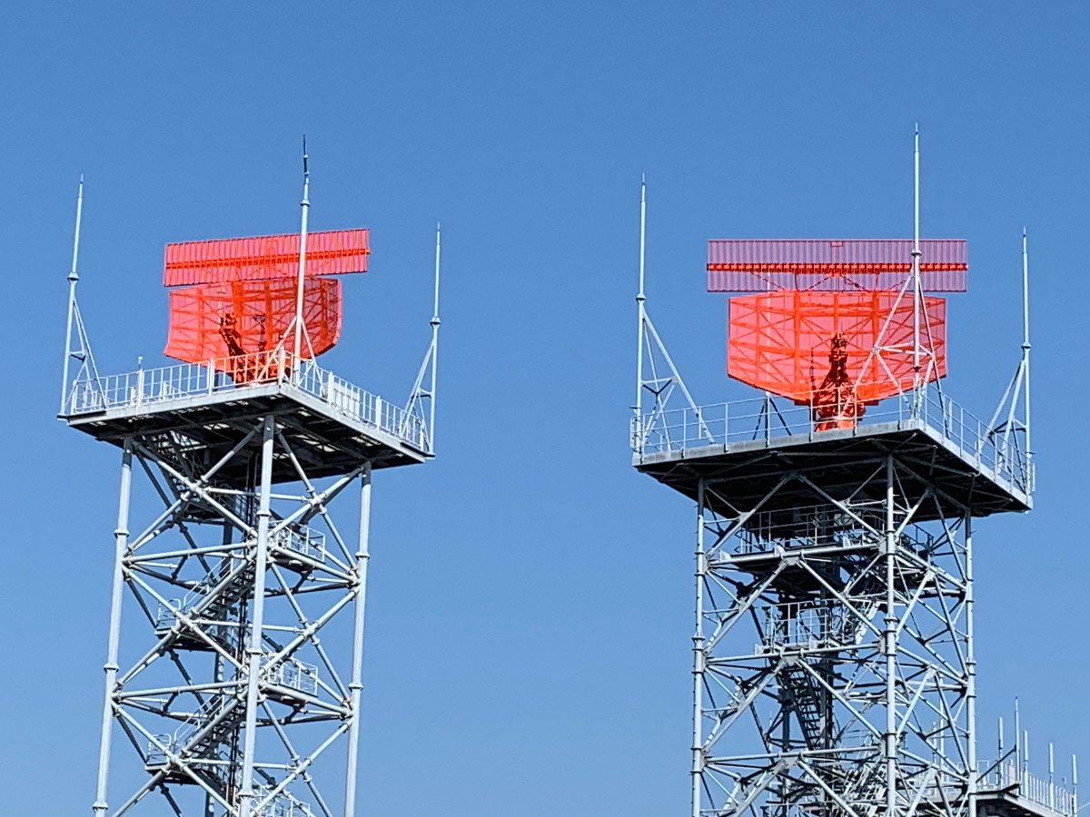
The narrow beam comes from a parabolic reflector antenna. A feed at the focus illuminates the reflector, which sends the energy out as parallel rays in phase, concentrated into a narrow beam of high gain: more range and better bearing resolution. For a given wavelength, a larger reflector gives a narrower beam. An airborne weather radar, limited by the size of the nose, forms a pencil beam 3° to 5° wide; a surface movement radar working at about 2 cm achieves 0.2° to 1°. An ATC surveillance reflector is shaped so that its beam is narrow in azimuth but spread vertically, covering aircraft at many heights in one sweep, and the flat bar of the SSR antenna usually sits on top and turns with it.
The rotation rate sets how often each target is updated: a long-range surveillance radar turns at 5 to 6 rpm, an aerodrome surface radar at 60 rpm.
Displays and moving target indication
The classic radar display is the plan position indicator (PPI): a map-like plan view with the radar at the centre, across which a trace rotates in step with the antenna. Each echo is painted at its range along the trace, so range and bearing can be read against range rings and a bearing scale. Modern ATC displays show processed plots and labels, combining primary radar with SSR and ADS-B, but the geometry is the same.
Raw echoes include clutter from the ground, buildings, the sea, precipitation and birds, which can hide an aircraft. Moving target indication (MTI) removes echoes that do not move. It compares successive returns, using the phase or Doppler shift of the echo, cancels those that stay the same from pulse to pulse and keeps those that change. An aircraft crossing the beam at right angles, with almost no speed towards or away from the radar, can be weakened or lost by the same process.
When the primary radar fails, only aircraft with a working transponder or ADS-B remain on the controller's screen, and the FAA's controllers say so: "primary radar out of service".
Reflection, second-trace returns and masking
How much energy a target returns depends on its size compared with the wavelength, its material and its aspect. Rough surfaces, such as land or a choppy sea, scatter energy in all directions and some comes back to the antenna. A smooth surface, such as a calm sea, gives specular reflection: like a mirror, it sends the beam away at the angle at which it arrived and returns almost nothing.
Second-trace returns come from targets beyond the maximum unambiguous range. The echo of one pulse arrives after the next pulse has been transmitted, and the radar times it from the wrong pulse, painting the target at a false, short range. They are most likely when unusual propagation, such as super-refraction under a temperature inversion, lets the radar see much further than its design range (see radio wave propagation). The cure is to jitter or stagger the PRF: genuine echoes stay at the same range from pulse to pulse, while second-trace echoes jump about and are rejected.
Terrain masking follows from line-of-sight propagation. Hills and buildings cast radar shadows in which low aircraft cannot be seen, and the lowest level covered rises with distance from the radar head, so an aircraft at low level in hilly country can drop out of cover well inside the radar's nominal range.
Surveillance and surface movement radars
Each ground radar trades range against resolution to suit its job. Typical figures quoted in ATPL training texts:
| Radar | Typical range | Wavelength | Pulse width | Other features |
|---|---|---|---|---|
| Long-range area surveillance | En-route distances | 10 to 50 cm | 2 to 4 µs | 300 to 400 pps, 5 to 6 rpm |
| Terminal area surveillance | Up to about 75 NM | 10, 23 or 50 cm | 1 to 3 µs | TMA traffic, usually with SSR |
| Aerodrome surveillance | About 25 NM | 3 or 10 cm | 0.5 to 1 µs | Vectoring to final, surveillance radar approaches |
| Aerodrome surface movement indicator (ASMI) | 2.5 to 6 NM | 1.75 to 2 cm (15 to 17 GHz) | About 0.03 µs | 4,000 to 20,000 pps, 60 rpm, beam 0.2° to 1° |
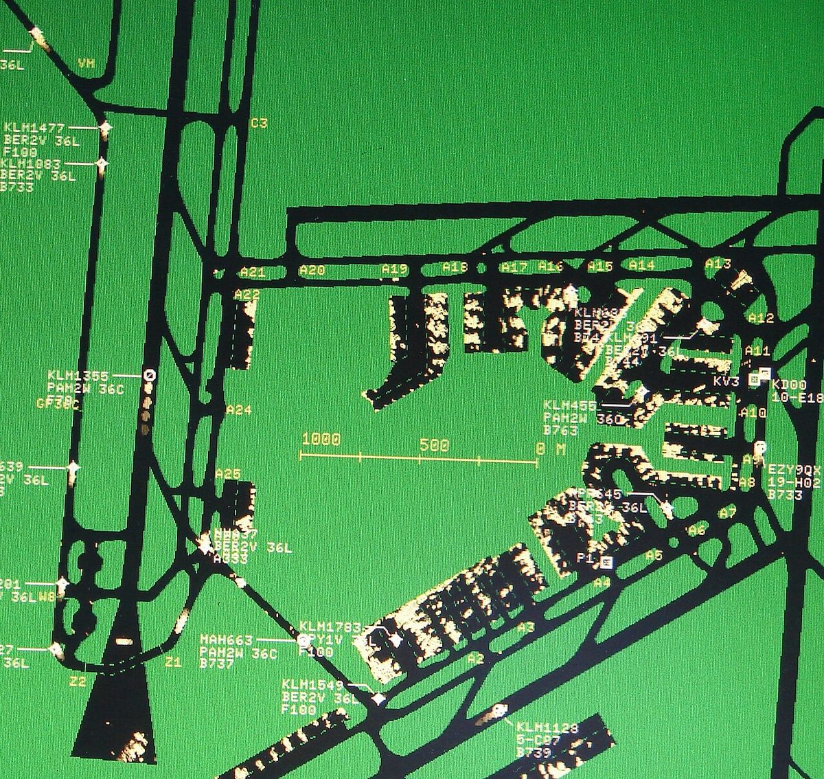
Long-range radars use long wavelengths to see through rain, long pulses for energy and a low PRF for range. The aerodrome surface movement indicator (ASMI) does the opposite: very short pulses, a narrow beam, a high PRF and a fast scan give a detailed, rapidly updated picture of the runways and taxiways, over a few miles only.
The aerodrome surveillance radar, called airport surveillance radar (ASR) by the FAA, also supports the surveillance radar approach (SRA), in which the controller gives guidance in azimuth only, with no glide path, and the approach ends at a stated distance from touchdown. In the FAA's ASR approach the controller also gives the position each mile and, on request, recommended altitudes. Training material gives system minimum descent heights of 250 ft for an SRA terminating at 0.5 NM, 300 ft at 1 NM and 350 ft at 2 NM. A precision approach radar (PAR), working at about 3 cm, adds elevation, and the controller talks the pilot down the glide path. Landing clearance is normally obtained by 4 NM from the threshold; a pilot who has not received it at 2 NM begins the missed approach (see radar services and vectoring).
Doppler effect and Doppler navigation
The Doppler effect is the change in received frequency when transmitter and receiver move relative to each other: the frequency rises as they close and falls as they separate. The Doppler shift is proportional to the component of relative velocity along the line joining them, so a target crossing at right angles produces none. A radar echo is shifted twice, on the way to the moving target and on the way back, so its shift is double that of a one-way link. The principle drives MTI, the turbulence and windshear modes of weather radar and the Doppler VOR.
A Doppler navigation system is a self-contained radar dead-reckoning aid that needs no ground stations. It directs beams down at the ground, typically four, pointing forwards and backwards on each side in what is called a Janus array, after the Roman god who looks both ways. The echoes of the forward beams rise in frequency and those of the rearward beams fall, in proportion to the aircraft's speed over the ground; comparing the two cancels most of the error that a change in pitch attitude would otherwise introduce. The difference between the beams on the left and right reveals the drift angle. Groundspeed and drift, combined with heading from the compass system, give track, and a computer keeps a dead-reckoning position.
Accuracy depends on the surface below: over a calm sea, specular reflection sends the beams away and the returns can be lost. The dead-reckoning position also drifts, and the FAA's AIM describes Doppler as less accurate than an inertial system and in need of periodic updates from an external reference on long flights. Inertial systems and GNSS have largely replaced it.
Exam tip: Doppler navigation measures groundspeed and drift directly; it needs heading from a compass to give a track. Specular reflection over a calm sea is its classic weakness.
Frequently asked questions
What is a radar mile?
A radar mile is the time a radar pulse takes to travel one nautical mile to a target and back, about 12.36 microseconds. Dividing an echo's delay in microseconds by 12.36 gives the target's range in nautical miles, so an echo arriving 900 microseconds after transmission comes from about 73 NM. The same figure is used in DME, where the ground beacon also adds a fixed delay of 50 microseconds before replying.
How does pulse repetition frequency affect maximum radar range?
Each echo must return before the next pulse is sent, otherwise the radar cannot tell which pulse it belongs to. The interval between pulses, the reciprocal of the PRF, therefore sets the maximum unambiguous range: about 81,000 divided by the PRF gives it in nautical miles. A radar transmitting 500 pulses per second can range to about 162 NM, and one that must reach 200 NM cannot exceed about 405 pulses per second.
What determines the minimum range and the resolution of a radar?
Mainly the pulse width. The receiver is blanked while a pulse is transmitted, and each microsecond of pulse is 300 m long, so the minimum range is 150 m per microsecond of pulse width. Two targets on the same bearing closer together than half the pulse length merge into one echo, which sets range resolution. Bearing resolution depends on the beam width. Short pulses and narrow beams, easier at high frequencies, give the sharpest picture.
What are second-trace returns on a radar?
They are echoes from targets beyond the radar's maximum unambiguous range. The echo arrives after the next pulse has been transmitted, so the radar times it from the wrong pulse and displays the target at a false, much shorter range. They become more likely when super-refraction extends radar range. Varying the interval between pulses, called PRF jitter or stagger, makes second-trace echoes jump in range from sweep to sweep so that they can be rejected.
What is the difference between primary and secondary radar?
Primary radar detects the echo of its own transmission from the aircraft's skin, so it sees every reflecting object, including weather, terrain and birds, but cannot identify an aircraft or give its height. Secondary radar interrogates the aircraft's transponder, which replies on another frequency with identity and pressure altitude. Each path is one-way, so secondary radar needs far less power: doubling a primary radar's range takes sixteen times the transmitter power.
How does a Doppler navigation system measure groundspeed and drift?
It directs radar beams down to the ground, typically four in a Janus array pointing forwards and backwards on each side. The echoes of the forward beams rise in frequency and those of the rear beams fall in proportion to groundspeed, and comparing the two cancels most of the error from pitch attitude. The difference between the left and right beams gives the drift angle. With heading from the compass, the system keeps a dead-reckoning position without any ground station.
Test yourself on Radar Principles
The v1prep banks cover this topic in General and Radio Navigation (061/062), with a worked explanation for every answer. EASA ATPL, PPL, IR and CPL, the FAA written tests and A320/B737 type ratings.
Start practising →Sources and further reading
- FAA Instrument Flying Handbook (FAA-H-8083-15B), Chapter 9, Navigation Systems
- FAA Aeronautical Information Manual, Chapter 1 Section 1 (1-1-16, Doppler Radar)
- FAA Aeronautical Information Manual, Chapter 4 Section 1 (4-1-15, Radar Traffic Information Service)
- FAA Aeronautical Information Manual, Chapter 5 Section 4 (5-4-11, Radar Approaches)
- ICAO Doc 4444, Procedures for Air Navigation Services, Air Traffic Management (PANS-ATM), 16th edition, as published by Airservices Australia
- SKYbrary, Primary Surveillance Radar (PSR)
Library articles are written for study and exam preparation. They do not replace your aircraft's approved documentation, your operator's procedures or the regulations themselves.