Continuous Descent Final Approach (CDFA)
A continuous descent final approach (CDFA) is a technique for flying the final segment of a non-precision approach as a continuous descent, without level-off, from at or above the final approach fix altitude to about 50 ft above the landing threshold or the flare point, with the go-around decision taken at a derived decision altitude.
A non-precision approach gives lateral guidance only and ends at a minimum descent altitude (MDA), a floor below which the aircraft may not go without the required visual reference. How the aircraft gets down to that floor is left to technique. The traditional way is dive and drive: descend promptly to each charted altitude, then fly level at the MDA towards the missed approach point, looking for the runway. The alternative is the continuous descent final approach (CDFA), in which the whole final segment is flown on a constant angle, as if the approach had a glide path.
EASA defines CDFA as a technique, consistent with stabilised approach procedures, for flying the final segment of a non-precision approach as a continuous descent without level-off, from an altitude at or above the final approach fix altitude to a point about 15 m (50 ft) above the landing threshold or where the flare begins. Its Air Operations rules require commercial operators to fly non-precision approaches with CDFA unless the authority approves another technique for a particular runway. The FAA recommends the technique through AC 120-108.
Dive and drive versus CDFA
Dive and drive keeps the aircraft as low as the procedure allows for as long as possible. After each fix it descends quickly to the next minimum altitude, levels off, and finally drives along at the MDA until the runway appears or the missed approach point is reached. The result is a series of thrust, attitude and often configuration changes close to the ground, a long level segment at low altitude, and a steep or late descent when the runway finally appears. Crews are tempted to push below the MDA to find the lights, and a go-around from level flight at the MDA starts low and far from the runway. Profiles of this kind recur in controlled flight into terrain accidents, and the Flight Safety Foundation's approach-and-landing accident reduction work made constant-angle non-precision approaches one of its main recommendations.
The CDFA flies the approach the way an ILS is flown: configured and on speed before the final descent, one constant descent angle and rate, and a single decision point. It is the non-precision form of the stabilised approach. EASA's AMC accepts that ATC or the operator's procedures may require a higher speed during a CDFA, but speed must then be stabilised no later than 500 ft above threshold elevation. Modern aircraft fly the path with coded modes, such as FINAL APP on the A320 or the FMS landing system (FLS), certified for VOR, VOR/DME, NDB and RNAV approaches with LNAV minima, or Boeing's integrated approach navigation, which presents a non-precision approach with ILS-like deviations.
The 3-degree path and descent gradient
The normal CDFA path is about 3°, the same 3-degree glide path as a standard ILS. A 3° path descends about 318 ft per nautical mile, a descent gradient of 5.2%, or roughly 1 in 19. PANS-OPS takes 5.2% as the optimum gradient for a non-precision final and 6.5%, just under 400 ft per NM, as the maximum, and places the final approach fix ideally 5 NM from the threshold and not more than 10 NM. AIP France marks non-precision finals steeper than 6.5% for Categories A and B, or 6.1% for C and D, as needing appropriate aircraft and crew qualifications.
| Descent angle | Gradient | Height lost per NM |
|---|---|---|
| 3.0° | 5.2% | 318 ft |
| 3.5° | 6.1% | 372 ft |
| 3.7° | 6.5% | 395 ft |
Charts help the crew fly the path. FAA policy is to publish a vertical descent angle (VDA) with its threshold crossing height, typically 30 to 50 ft, on non-precision approaches, except those sharing a chart with vertically guided minima and on-airport procedures with no final approach fix or step-down fix; RNAV charts give the angle to the hundredth of a degree. The VDA is advisory: it does not change the approach into one with vertical guidance and gives no obstacle protection below the MDA. European charts typically add a table of distance against altitude. On the LOC Y RWY 18 at Chambery, for example, the crew should pass 4,087 ft at 7 NM, which the table also gives as a height of 3,318 ft above the threshold.
Rate of descent and the 3:1 rule
The rate of descent that holds a path is the gradient multiplied by the groundspeed in nautical miles per minute. For 3° that is about 318 × GS ÷ 60, or roughly 5.3 times the groundspeed; the quick rule is five times the groundspeed.
| Groundspeed | Exact, 3° | Rule of thumb (5 × GS) |
|---|---|---|
| 90 kt | 477 ft/min | 450 ft/min |
| 120 kt | 637 ft/min | 600 ft/min |
| 140 kt | 743 ft/min | 700 ft/min |
Because it depends on groundspeed, the rate changes with the wind: a headwind needs less, a tailwind more. Charts often give a table of rates for the published angle; the Nantes RNP Y RWY 21, with a 3.1° (5.4%) final, lists 710 ft/min at 130 kt.
The 3:1 rule is the planning version of the same geometry: 3 NM for every 1,000 ft to lose, about 330 ft per NM, slightly steeper than 3°. A companion rule divides the height above the threshold by 300 to give the distance in NM, which assumes 300 ft per NM and is slightly shallower. The two bracket the true value: a 3° path passes 1,500 ft above the threshold about 4.7 NM out, where the 3:1 rule gives 4.5 NM and division by 300 gives 5 NM.
Step-down fixes
A step-down fix (FAA: stepdown fix) is a fix in the final approach segment after which a lower altitude is permitted, because a controlling obstacle has been passed. The aircraft may not descend below the step-down altitude until the fix has been identified with the required equipment, and charts often publish two sets of minima, a lower one for aircraft able to identify the fix and a higher one for those that cannot. Under the FAA's AIM, step-down altitudes in the final segment apply only to lines flown to an MDA; they may be annotated "LOC only" or "LNAV only", and they do not bind aircraft using a DA line with approved vertical guidance.
In a CDFA a step-down fix is a checkpoint, not a level-off. The published angle is computed from the final approach fix or a step-down fix to the threshold crossing height, so a path flown on it normally passes each step-down fix at or above its altitude. The crew still checks the altimeter at each fix and at each distance in the table, and never trades a step-down altitude for a smooth path.
Derived decision altitude
The MDA is a floor, but an aircraft cannot turn a descent into a climb without sinking a little further. A crew that waited until the MDA to go around would therefore break it. The CDFA answer is a derived decision altitude (DDA): the MDA plus an increment set by the operator, commonly 50 ft. If the required visual reference is not established at the DDA, the go-around begins there, and the momentary sink keeps the aircraft at or above the MDA, as the rules require.
The missed approach point still limits the approach laterally. If the aircraft reaches it before the DDA, for example because the path started high, the go-around begins at the missed approach point. An aircraft that goes around early flies the published track to the missed approach point before turning, unless ATC clears otherwise, because the protected area makes no allowance for early turns. The DDA is not printed on the chart, and like the MDA it must be corrected for cold temperature when the conditions call for it (see minimum safe altitudes). With the visual reference in sight at or before the DDA, the aircraft continues its descent on the same path to the runway.
Visual descent point
The FAA's visual descent point (VDP) is a defined point on the final approach course of a straight-in non-precision approach from which a stabilised visual descent from the MDA to the touchdown point may begin. Charts mark it with a bold V, identified by DME or RNAV along-track distance; on an RNAV approach it serves only the lines flown to an MDA, such as LNAV, and it is not part of the GPS waypoint sequence. Its distance is based on the lowest MDA and harmonised with the angle of the visual glide slope indicator, or with the VDA where there is none. A pilot should not descend below the MDA before reaching the VDP, and descent between the VDP and the missed approach point may be inadvisable or impossible. Where no VDP is published, the height above touchdown divided by 300 gives its approximate distance in NM: 1.5 NM for a height of 450 ft.
On a CDFA flown on the published angle, the aircraft arrives at the MDA close to the VDP, which is why the two ideas fit together. Where obstacles penetrate the visual segment, FAA charts replace the VDA with the note "Visual Segment – Obstacles", and following an advisory path below the MDA there could lead into them.
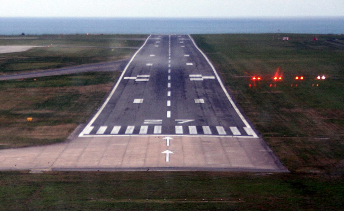
CDFA on a VOR approach
Consider a VOR/DME approach whose DME reads distance to the threshold, threshold elevation 200 ft, a final approach fix at 5 DME crossed at 1,840 ft, a published angle of 3.0° with a 50 ft threshold crossing height, a step-down fix at 3 DME with a minimum of 1,100 ft, and an MDA of 700 ft (HAT 500 ft). The operator's add-on of 50 ft gives a DDA of 750 ft.
| DME | 5 | 4 | 3 | 2 | 1 |
|---|---|---|---|---|---|
| Altitude on a 3° path | 1,840 ft | 1,520 ft | 1,210 ft | 890 ft | 570 ft |
At 120 kt groundspeed the crew sets about 640 ft/min, or a 3.0° flight path angle, as the aircraft crosses the fix, fully configured and on speed. The path passes the step-down fix 110 ft above its minimum, and each DME reading is checked against the table: above it, increase the rate slightly; below it, reduce the rate, never below the charted minimum altitude. The aircraft reaches the DDA about 1.6 NM from the threshold. With the runway in sight it continues on the same path; without it, it goes around at 750 ft and flies the missed approach, turning no earlier than the missed approach point. Timing backs up the distances: at 120 kt each nautical mile takes 30 seconds, so the aircraft should pass 3 DME one minute after the fix.
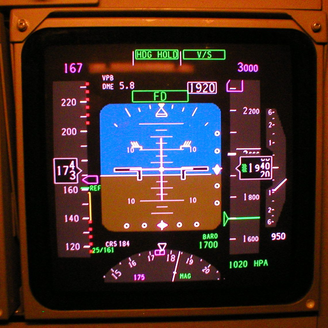
A VOR adds two cautions. Its guidance is angular and far coarser than a localiser, about 2° per dot on a five-dot indicator, so the lateral path deserves as much attention as the vertical one. And where a suitable RNAV system flies the final segment, the AIM requires the VOR to be operating and monitored for course alignment unless the procedure title includes "or GPS".

Frequently asked questions
What is a continuous descent final approach?
It is a way of flying the final segment of a non-precision approach, such as a VOR, NDB, localiser or LNAV approach, as a constant-angle descent from the final approach fix to about 50 ft over the threshold, like an ILS, instead of stepping down and levelling at the minimum descent altitude. The crew goes around at a derived decision altitude slightly above the MDA if the required visual reference is not in sight.
Why is dive and drive considered dangerous?
Diving to each step-down altitude and then flying level at the minimum descent altitude keeps the aircraft low for longer, adds thrust, attitude and configuration changes close to the ground, and leaves a steep or late descent once the runway appears. It also tempts crews below the MDA to look for the lights. Such profiles appear repeatedly in controlled flight into terrain accidents, which is why EASA requires the CDFA technique for commercial operations.
What is a derived decision altitude?
A derived decision altitude (DDA) is the altitude at which a crew flying a CDFA starts the go-around if the required visual reference is not established. The MDA is a floor, and an aircraft transitioning from a descent to a climb sinks a little further, so operators add an increment, commonly 50 ft, to the MDA. Going around at the DDA keeps the aircraft at or above the MDA. It is set by the operator, not printed on the chart.
How do you calculate the rate of descent for a 3 degree approach?
A 3° path descends about 318 ft per nautical mile, so the rate of descent in ft/min is that gradient multiplied by the groundspeed in NM per minute. The quick rule is five times the groundspeed in knots. At 90 kt it gives 450 ft/min against an exact 477 ft/min; at 140 kt, 700 against 743. Charts often print a rate of descent table for the published angle, and a tailwind needs a higher rate than a headwind.
What is a visual descent point?
A visual descent point (VDP) is a defined point on the final approach course of a straight-in non-precision approach from which a stabilised visual descent from the MDA to the touchdown point can begin. FAA charts mark it with a bold V, identified by DME or RNAV distance. Pilots should not descend below the MDA before reaching it. Where none is published, the height above touchdown divided by 300 gives an approximate distance in NM.
Test yourself on Continuous Descent Final Approach (CDFA)
The v1prep banks cover this topic in General and Radio Navigation (061/062), with a worked explanation for every answer. EASA ATPL, PPL, IR and CPL, the FAA written tests and A320/B737 type ratings.
Start practising →Sources and further reading
- EASA, AMC and GM to Part-CAT (AMC1 CAT.OP.MPA.115, Approach flight technique)
- EASA, Easy Access Rules for Air Operations (Regulation (EU) No 965/2012)
- FAA Aeronautical Information Manual, Chapter 5 Section 4 (stepdown fixes, visual descent point, vertical descent angle)
- 14 CFR 91.175, Takeoff and landing under IFR
- Flight Safety Foundation, ALAR Briefing Note 7.1, Stabilized Approach
- ICAO Doc 8168, Procedures for Air Navigation Services, Aircraft Operations (PANS-OPS), and Annex 6, Operation of Aircraft
- FAA Instrument Procedures Handbook (FAA-H-8083-16B)
Library articles are written for study and exam preparation. They do not replace your aircraft's approved documentation, your operator's procedures or the regulations themselves.