GNSS Errors and Dilution of Precision
GNSS position error is the combined effect of the errors in each measured satellite range, from orbit and clock data, atmospheric delay, multipath and receiver noise, magnified by the dilution of precision, a factor that expresses how the geometry of the satellites in view turns range errors into position error.
A GNSS receiver computes its position from ranges measured to satellites, and every range contains small errors. Two things decide how large the resulting position error is: the size of those range errors, the error budget, and the geometry of the satellites in view, expressed as the dilution of precision (DOP). As a working rule, position error is roughly the range error multiplied by the DOP. Over both hangs a third threat that has become an everyday operational problem: interference, accidental or deliberate, in the form of jamming and spoofing.
The distinction matters to the crew. Range errors are beyond their control but are reduced by the receiver, by dual-frequency signals and by augmentation. Geometry changes predictably as the satellites move and is what integrity prediction checks (see GNSS integrity and RAIM). Interference must be recognised and managed. How the system works is covered in GNSS.
GNSS error budget
ICAO's standard for the GPS Standard Positioning Service is an accuracy of 13 m horizontally and 22 m vertically, 95% of the time, and typical performance is better. The contributions usually quoted in ATPL training texts for a single-frequency receiver are:
| Error source | Typical contribution | Cause | Reduced by |
|---|---|---|---|
| Ionospheric delay | Up to 5 m | Charged particles slow the signal | Dual frequency; SBAS and GBAS corrections |
| Ephemeris error | About 2.5 m | Actual orbit departs from the broadcast one | Differential corrections |
| Satellite clock error | About 1.5 m | Residual drift of the atomic clocks | Broadcast and differential corrections |
| Multipath | About 0.6 m | Reflected copies of the signal | Antenna siting; receiver processing |
| Tropospheric delay | About 0.5 m | Pressure, temperature and humidity | Receiver model; GBAS |
| Receiver noise | About 0.3 m | Thermal noise in the receiver | Receiver design |
The receiver's own clock bias, far larger than any of these, is not in the table. It is common to every range and is solved as the fourth unknown, which is why four satellites are needed for a three-dimensional fix. Selective Availability, the deliberate degradation of civil accuracy to about 100 m, was discontinued on 1 May 2000.

Ephemeris and clock errors
The ephemeris is the set of orbital data each satellite broadcasts so that the receiver knows where the satellite was when it transmitted. It is a prediction, computed by the control segment and uploaded to the satellite, and the real orbit departs from it under the pull of the sun, moon and planets and the pressure of solar radiation. The resulting ephemeris error, about 2.5 m, is an error in the assumed position of the satellite, and so an error in range.
Each satellite carries three or four rubidium or caesium atomic clocks, good to about a nanosecond. They are not adjusted in orbit: the control segment measures their offset and the satellite broadcasts it as a correction. Timing errors translate directly into distance, because a signal covers about 30 cm in a nanosecond; a residual clock error of 5 ns is already 1.5 m of range.
Both errors are the same for every user who sees the satellite, which makes them ideal for differential correction. SBAS reference stations measure satellite clock and ephemeris errors and broadcast corrections, and a GBAS station at an airport removes them, with most of the atmospheric delay, for aircraft nearby (see SBAS and GBAS augmentation). A grossly wrong ephemeris or clock is a different matter, one of integrity: the AIM notes that up to two hours can pass before the control segment detects and corrects an erroneous satellite transmission.
Ionospheric and tropospheric delay
GNSS signals are slowed on their way down through the atmosphere, and the receiver, which assumes they travelled at the speed of light, measures ranges that are too long.
The ionosphere, the ionised upper atmosphere, causes the largest single error for a single-frequency receiver, up to about 5 m. The delay varies with solar activity, time of day and the satellite's elevation, so the model broadcast in the navigation message removes only part of it. It is inversely proportional to the square of the frequency, so a receiver comparing two frequencies, such as L1 and L5, can measure it and cut the error below about 0.5 m. SBAS broadcasts an ionospheric correction for single-frequency users. Disturbed ionospheric conditions can still deny SBAS vertical guidance, the reason for the FAA's "WAAS MAY NOT BE AVBL" NOTAMs.
The tropospheric delay arises in the lower atmosphere, where pressure, temperature, density and humidity change the propagation speed. It is small, about 0.5 m and up to a few metres in extreme conditions, but, unlike the ionospheric delay, it does not depend on frequency, so dual-frequency reception does not remove it. Receivers apply a tropospheric model, and GBAS, whose reference receivers see nearly the same atmosphere as an aircraft nearby, removes most of the rest.
Both delays are larger for satellites low in the sky, whose signals take a long, slanting path through the atmosphere.
Multipath
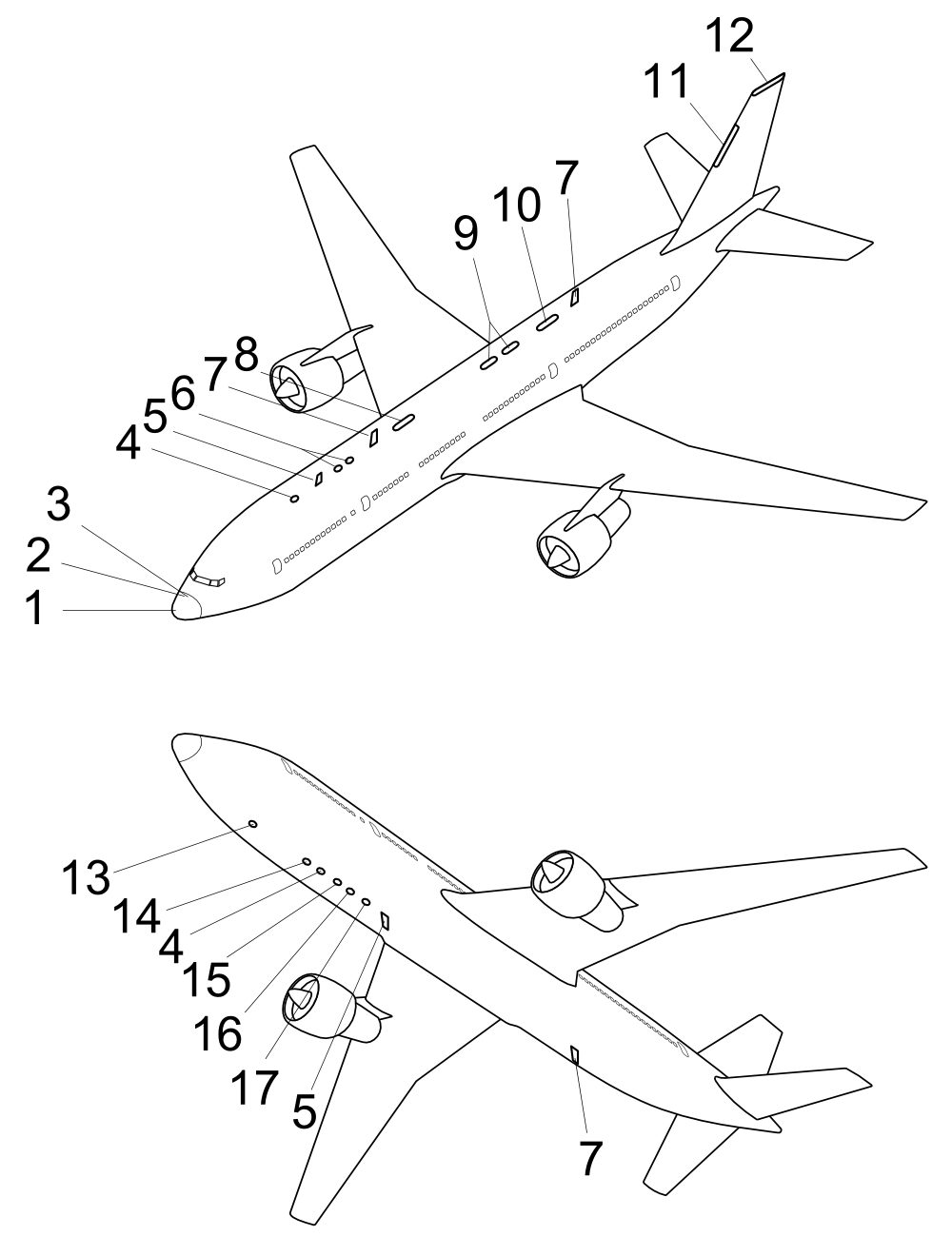
Multipath occurs when the antenna receives a satellite signal both directly and as reflections from the fuselage, the wings, the ground or nearby buildings. The reflected copies arrive late, having travelled further, and the receiver may lock on to a delayed copy or be pulled by it, measuring a range that is too long. In flight the multipath error is small, about 0.6 m, but it is worst on or near the ground among hangars, terminals and rising terrain. GNSS antennas are therefore mounted on top of the fuselage, where the airframe masks least of the sky and reflects least into the antenna; on the A320, both GPS antennas are on the upper forward fuselage. Receiver signal processing rejects much of what remains.
Receiver noise, about 0.3 m, is the thermal noise of the receiver's own circuits, which blurs the timing measurement; only receiver design reduces it.
The airframe can also block signals altogether. The AIM warns that antenna location, the satellites' positions relative to the horizon and the aircraft's attitude all affect reception, and that pitch and bank changes can cause the loss of satellites and integrity warnings.
Mask angle
The mask angle is the lowest elevation above the horizon at which the receiver uses a satellite. Aviation receivers typically use 5°; some applications use 7.5° or 10°. Below it, the long path through the atmosphere increases the ionospheric and tropospheric delays and refraction, and multipath from the ground is most likely.
The mask is a compromise. Low satellites are exactly those that give the best horizontal geometry, so a higher mask angle removes error but raises the DOP and leaves fewer satellites for integrity monitoring. In a turn, the lowered wing and the fuselage can also mask satellites that are above the nominal mask angle on that side.
Exam tip: the typical GNSS mask angle is 5°. All-in-view receivers track every satellite above it and use them all in the solution.
Satellite geometry and DOP
Each measured range places the aircraft on a sphere around a satellite. Because every range contains some error, each sphere is really a shell of some thickness, and the fix lies where the shells overlap. When the satellites are spread widely across the sky, the shells cross at large angles and the overlap is small. When they are bunched in one part of the sky, the shells cross at shallow angles and the overlap is long and thin, so the same range errors produce a much larger position error. Each range is as good as before; the fix is not.
Dilution of precision (DOP) expresses this effect as a single number, the factor by which geometry multiplies range error into position error. Values of 1 to 3 indicate good geometry, and above about 6 geometry is poor. With a range error of 5 m, for example, an HDOP of 1.2 gives roughly 6 m of horizontal error, and an HDOP of 4 about 20 m.
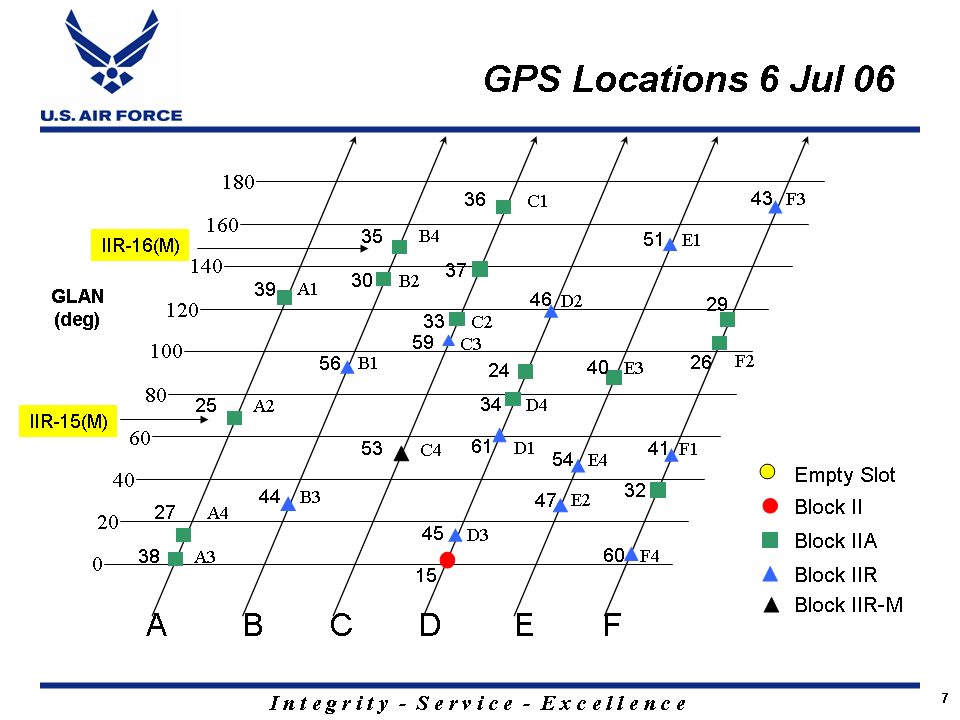
The best geometry has one satellite directly overhead and the others spread evenly near the horizon, for example three about 120° apart. The worst has them clustered together. Because the satellites move continuously, DOP changes from minute to minute and from place to place, and the AIM lists unsuitable geometry, not only too few satellites, as a cause of integrity outages. A receiver that has to choose uses the combination with the lowest DOP; modern all-in-view receivers use every satellite above the mask angle, which normally keeps DOP low.
GDOP, PDOP, HDOP, VDOP and TDOP
DOP is quoted separately for different parts of the solution:
| Term | Name | Applies to |
|---|---|---|
| HDOP | Horizontal dilution of precision | Latitude and longitude |
| VDOP | Vertical dilution of precision | Height |
| PDOP | Position dilution of precision | Three-dimensional position, HDOP and VDOP combined |
| TDOP | Time dilution of precision | The receiver clock solution |
| GDOP | Geometric dilution of precision | Position and time together, PDOP and TDOP combined |
The components combine as squares: PDOP² = HDOP² + VDOP², and GDOP² = PDOP² + TDOP².
VDOP is normally larger than HDOP. Every satellite in view is above the horizon, so heights are measured from one side only, whereas horizontally the satellites can surround the receiver. This is why the SPS standard allows 22 m vertically against 13 m horizontally, and one reason unaugmented GNSS height is not accepted for vertical guidance. GNSS height is also measured above the WGS-84 ellipsoid, which differs from mean sea level by up to about 100 m, so it never replaces the barometric altimeter for terrain clearance.
Jamming and spoofing
GNSS signals reach the aircraft at very low power, so they are easily overwhelmed. The AIM lists sources of unintentional interference: radars, microwave links, ionospheric effects, solar activity, multipath, satellite communications, GPS repeaters and even systems on board the aircraft. These are usually local and intermittent. The growing concern is deliberate GNSS interference:
- Jamming transmits noise or signals strong enough to drown the satellites, so the receiver loses them and navigation fails or degrades.
- Spoofing transmits counterfeit satellite signals so that the receiver computes a false position or time, possibly without any warning.
Military receivers are protected against spoofing by the encrypted Y code; civil receivers using the open signals are not. Spoofing is especially dangerous for integrity monitoring: RAIM looks for one range that disagrees with the others, and a spoofer that falsifies all of them consistently leaves nothing to disagree.
In the United States, military GPS testing is announced by NOTAMs that can cover very large areas. The AIM's example warns that GPS, including WAAS, GBAS and ADS-B, may be unavailable within 468 NM of the test site at FL400, shrinking to 327 NM at 50 ft above the ground, because the jammer's line of sight reaches further at height.
The effects go well beyond the navigation display. The AIM lists, among others, loss of GNSS and hybrid GNSS/inertial navigation and of RNP capability, unreliable terrain warnings, wrong positions on moving maps, lost or erroneous ADS-B, autotuning that fails to select nearby navaids when the aircraft has been spoofed off track, erroneous FMS indications such as an insufficient fuel warning, wrong aircraft clocks that prevent CPDLC logon, and false wind and groundspeed. The FAA's guidance on recognition and response:
- Before flight: know the risk areas, check NOTAMs, plan fuel contingencies, and plan to use conventional navaids and approaches at the destination.
- In flight: watch for changes in actual navigation performance, clock changes, FMS position errors, large shifts in GPS position, position warnings on the PFD or ND, and other aircraft reporting problems. Verify the position against VOR and DME, be ready to revert to conventional procedures, and tell ATC promptly, except when crossing a NOTAMed test area without needing assistance.
- After flight: record the event in the maintenance log so that faults are cleared, and report it.
Because interference and test events have become more common, the FAA requires air carriers and commercial operators flying IFR to keep a non-GPS navigation capability, for example DME/DME, inertial or VOR for the en-route and terminal phases, and VOR and ILS for the final approach.
Frequently asked questions
What is dilution of precision in GPS?
Dilution of precision (DOP) is a number describing how the geometry of the satellites in view magnifies ranging errors into position error. Satellites spread widely across the sky give a low DOP and a sharp fix; satellites clustered together give a high DOP and a poor fix, even though each range is as accurate as before. Values of 1 to 3 are good and above about 6 poor. Position error is roughly the range error multiplied by the DOP.
What is the difference between GDOP, PDOP, HDOP, VDOP and TDOP?
They describe different parts of the solution. HDOP applies to horizontal position, VDOP to height, and PDOP to three-dimensional position, combining the two. TDOP applies to the receiver's time solution, and GDOP combines position and time, that is PDOP and TDOP. VDOP is normally larger than HDOP because every satellite in view is above the horizon, which is why GNSS vertical accuracy is poorer than horizontal accuracy.
Why is GPS vertical accuracy worse than horizontal accuracy?
Every satellite a receiver can use is above the horizon, so heights are measured from one side only, while horizontally the satellites can surround the aircraft. The vertical dilution of precision is therefore normally larger than the horizontal, which is why the GPS Standard Positioning Service is specified to 22 m vertically but 13 m horizontally, 95 per cent of the time. GNSS height is also referenced to the WGS-84 ellipsoid, not mean sea level, so it never replaces the barometric altimeter.
What is the GNSS mask angle?
The mask angle is the lowest elevation above the horizon at which a receiver will use a satellite, typically 5 degrees in aviation and sometimes 7.5 or 10 degrees. Signals from lower satellites cross much more atmosphere and are prone to multipath from the ground, so their ranges are unreliable. The mask is a compromise, because low satellites also give the best horizontal geometry and add redundancy for integrity monitoring.
What is the difference between GPS jamming and spoofing?
Jamming overpowers the weak satellite signals with noise or stronger transmissions, so the receiver loses them and GNSS navigation fails or degrades. Spoofing transmits counterfeit satellite signals so that the receiver computes a false position or time, which may go unnoticed. Both can disrupt RNP capability, terrain warnings, ADS-B, aircraft clocks and wind computation. Crews cross-check with conventional navaids and inertial data and report anomalies to ATC.
Test yourself on GNSS Errors and Dilution of Precision
The v1prep banks cover this topic in General and Radio Navigation (061/062), with a worked explanation for every answer. EASA ATPL, PPL, IR and CPL, the FAA written tests and A320/B737 type ratings.
Start practising →Sources and further reading
- FAA Aeronautical Information Manual, Chapter 1 Section 1 (1-1-17 GPS, 1-1-18 WAAS)
- FAA Aeronautical Information Manual, Chapter 1 Section 2 (1-2-4, GPS jamming and spoofing)
- ICAO Annex 10, Aeronautical Telecommunications, Volume I, Radio Navigation Aids (GNSS standards; copy published by IACM Mozambique)
- US Department of Defense, GPS Standard Positioning Service Performance Standard, 5th edition (2020)
- FAA Instrument Flying Handbook (FAA-H-8083-15B), Chapter 9, Navigation Systems
- SKYbrary, Global Navigation Satellite System (GNSS)
Library articles are written for study and exam preparation. They do not replace your aircraft's approved documentation, your operator's procedures or the regulations themselves.