Localizer-Based Approaches (LOC, LDA, SDF and Back Course)
A localizer-based approach is a non-precision instrument approach that uses the lateral guidance of an ILS localiser, or of a similar localiser-type course, without an electronic glide path. It includes localiser-only and back-course approaches and, in the United States, approaches on the offset LDA and the wider SDF.
The localiser of an instrument landing system is the most precise lateral guidance most aircraft receive from the ground, and it remains useful without the glide path. A localizer-based approach uses that course, or one produced by a similar transmitter, to bring the aircraft down to a minimum descent altitude (MDA) with lateral guidance only. It is a non-precision approach, a 2D operation in current ICAO and EASA terms (see instrument approach procedures).
Four variants exist. The localiser-only (LOC) approach uses the front course of an ILS without its glide path, or a localiser installed on its own. The back course (BC) uses the signal radiated behind the localiser antenna to approach the opposite end of the runway. The localizer-type directional aid (LDA) and the simplified directional facility (SDF) are facility types described in the FAA's AIM whose courses need not be aligned with the runway. Each brings traps that an ILS does not: reverse sensing on the back course, offset courses that end away from the runway, and wider courses that allow less precision.
Localiser-only approaches
A localiser-only approach, often written LOC only, is flown when the glide path is out of service, when the aircraft cannot use it, or where none is installed. ICAO treats an ILS used in azimuth only as a non-precision aid. FAA charts usually combine the two procedures on one chart, titled for example "ILS or LOC RWY 14R", and the French AIP notes that ILS and LOC procedures may share a chart even when their final or missed approach segments differ.
Without the glide path, three things change:
- Minima. The LOC line gives an MDA rather than a decision altitude, and it is higher. On the ILS or LOC RWY 14R at Boeing Field, the Category A and B localiser minima are an MDA of 600 ft with an RVR of 4,000 ft, against a decision altitude of 308 ft on the ILS.
- Vertical path. Height is managed against fixes and distances. The final approach fix is the outer marker or a substitute, such as a DME fix or compass locator, and step-down fixes set minimum altitudes on the way down: at Boeing Field, after the final approach fix TOGAE, the aircraft stays at or above 1,080 ft until SOTEE, at 4.9 DME, before descending to the MDA.
- Missed approach point. The MAPt is a DME distance, a fix or a time from the final approach fix. Timing tables give the time for each groundspeed: on the Strasbourg ILS or LOC RWY 23, the 3.4 NM from the outer marker to the MAPt take 1 min 34 s at 130 kt; on the Port Angeles ILS or LOC RWY 9, the 6.2 NM from the final approach fix take 4 min 08 s at 90 kt. The table is entered with groundspeed, not indicated airspeed.
If the glide path fails during an ILS approach, the approach may continue as a localiser approach, provided the crew has the LOC minima, can identify the MAPt and respects the step-down altitudes; otherwise the missed approach is the safe choice. Descending on an imagined glide path is not permitted.
In FAA usage, an aircraft is established on the localiser when the deviation is within half full scale. Coverage is that of the ILS localiser: ICAO requires 25 NM within 10° of the course line and 17 NM between 10° and 35°, while the FAA guarantees 18 NM and 10 NM. Full scale is roughly 2.5° either side of the course, which makes the localiser about four times as sensitive as a VOR.
EASA requires non-precision approaches to be flown as a continuous descent final approach (CDFA) unless another technique is approved for the runway, and the FAA recommends the same technique (see CDFA). Airliners usually take lateral guidance from the localiser and vertical guidance from a computed path. The A320's FLS function covers LOC, ILS with the glide slope out and LOC B/C approaches, using the localiser laterally and the FMS vertically, whereas the FMGS NAV mode alone is not certified for the final approach of LOC, LOC B/C, LDA or SDF procedures. Boeing recommends LNAV or VOR/LOC as the 737's roll mode on LOC, SDF and LDA approaches.
Warning: a GNSS-based RNAV system does not replace the localiser. The FAA lets a suitable RNAV system substitute for a VOR or NDB in many cases, but not for lateral navigation on localiser-based courses, back courses included, without reference to raw localiser data, and LOC, LDA and SDF procedures cannot be flown as GPS overlays.
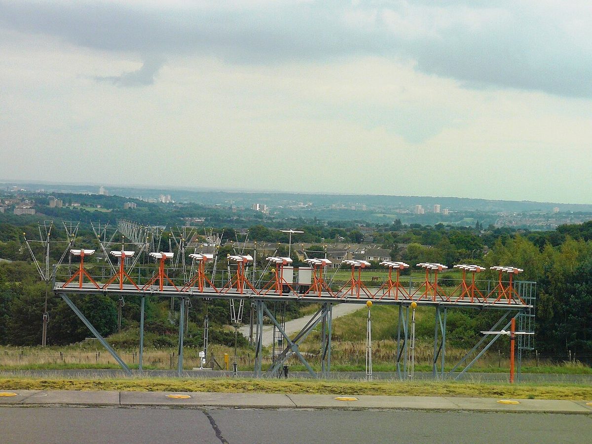
The localiser back course
The localiser antenna radiates both ways. Its front course serves the approach to the runway; behind the antenna the same pattern appears as a mirror image, forming the back course (BC), which the AIM defines as the course line along the extended centreline in the opposite direction to the front course. The localizer back course (localiser back course in British spelling, back beam in some UK texts) therefore lies over the approach to the reciprocal runway, and a back-course approach, also written backcourse approach and charted in the United States as a LOC BC procedure, uses it for a non-precision approach to that runway.
Rules differ between states. ATPL training material notes that the UK does not permit back-course approaches, while some other states allow them as non-precision approaches. The FAA allows back-course signals to be used for an approach only where a back-course procedure is published for the runway and ATC authorises it.
What the back course lacks:
- No glide path. The glide path antenna radiates towards the front course. False glide slope signals may exist in the back-course area and can even make the glide slope flag disappear, so the AIM tells pilots to disregard all glide slope indications on a back-course approach unless the chart specifies a glide slope. Some displays help: the 737's glideslope pointer is removed when the track differs by more than 90° from the front course set on the mode control panel.
- Different fixes. Where a back-course marker is installed, it normally marks the final approach fix where the descent begins, and it lights the white marker lamp. DME, from the ILS or from a separate facility, may also define the back-course final approach fix.
- Rising sensitivity. The localiser course width is tailored to the front-course threshold. On a back-course approach the aircraft flies towards the antenna itself, which stands beyond the stop end of the front-course runway and so lies close to the back-course threshold. The course narrows quickly as the aircraft nears it.
Reverse sensing and HSI setup
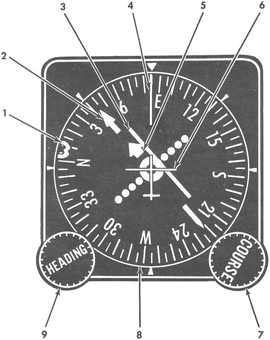
Reverse sensing is an indication that shows the course on the wrong side, and it comes from geometry, not from a fault. The localiser receiver's deviation signal depends only on which side of the centreline the aircraft is, defined as seen from the front-course approach, and a conventional course deviation indicator (CDI) shows that signal whatever the aircraft's heading. Flying inbound on the back course, or outbound on the front course, the aircraft faces the other way, so the needle lies away from the course and the pilot must fly away from the needle. The AIM describes this as necessary unless the aircraft's ILS equipment includes reverse sensing capability.
A horizontal situation indicator (HSI) removes the problem when correctly set. Its course pointer and deviation bar turn with the compass card, so with the published front course inbound set on the course pointer, the bar senses correctly in every direction, including inbound on the back course, where the course pointer points roughly towards the tail. Setting the back-course heading instead rotates the presentation through 180°: the bar still shows the right amount of displacement, but on the wrong side, and steering towards it takes the aircraft further off course.
| Leg flown | Conventional CDI | HSI with front course set |
|---|---|---|
| Front course inbound | Normal | Normal |
| Front course outbound | Reverse: fly away from the needle | Normal |
| Back course inbound | Reverse: fly away from the needle | Normal |
| Back course outbound | Normal | Normal |
Equipment with a back-course function reverses the sensing electrically. On the 737, the B/CRS position of the standby attitude indicator's approach selector reverses the localiser pointer and removes the glideslope pointer. Autopilots differ: the A320 has a LOC B/C mode, while Boeing's 737 procedure for a back-course approach sets the front course in the mode control panel course window, does not select VOR/LOC, and flies the approach in LNAV, because the autopilot cannot track a back course.
Flying a back-course approach
A typical sequence, to be adapted to the equipment and the operator's procedures:
- Confirm that a back-course procedure is published and authorised, and identify the localiser by its Morse identifier, which in the United States is I followed by three letters.
- Set the published front course inbound on the HSI course pointer, or brief reverse sensing if only a CDI is fitted. Select any back-course mode the equipment offers, and do not arm a mode that expects a glide path.
- Disregard glide slope indications unless the chart provides one, and plan the descent from the chart's fixes and distances, as a continuous descent where required.
- Keep corrections small as the aircraft nears the antenna and the course narrows.
- Without the required visual references at the MDA, or at the MAPt, fly the missed approach.
Aircraft systems may recognise the situation: on certain 737 variants, the "FIVE HUNDRED" radio altitude callout is given when a back-course approach is detected, as on any approach other than an ILS or GLS.
Localizer-type directional aid (LDA)
The localizer-type directional aid (LDA) gives a course of comparable use and accuracy to a localiser but is not part of a complete ILS, and its course is not aligned with the runway. The AIM sets the limits: straight-in minima may be published where the angle between the final approach course and the runway does not exceed 30°; beyond that, only circling minima are published. Because the course is offset, more manoeuvring is needed after becoming visual than after an ILS. An LDA course is usually more precise than the similar SDF.
A very small number of LDAs have a glide slope. Their charts carry the note "LDA/Glideslope" in the plan view and separate minima lines, S-LDA/GS and S-LDA; the FAA classes the vertically guided version as an approach with vertical guidance (APV), not a precision approach. Offset courses of this kind are also used for simultaneous offset instrument approaches (SOIA) to closely spaced parallel runways. The pilot on the offset course must see the runway environment before its decision altitude and, if ATC has said the traffic on the straight-in approach is a factor, must also see that aircraft and report it to ATC.
Simplified directional facility (SDF)
The simplified directional facility (SDF) provides a final approach course similar to a localiser's, in the same band of 108.10 to 111.95 MHz, but no glide slope. The differences all concern precision:
- The course width is fixed at 6° or 12°, whichever gives the best flyability and course quality, whereas a localiser is tailored to about 700 ft at the threshold, typically 3° to 6°.
- The antenna may be offset from the runway centreline. The angle between the final approach course and the runway is generally not more than 3°, but because the course originates at the antenna, an aircraft continuing past the threshold along it is led towards the antenna, not along the runway.
- Usable off-course indications are limited to 35° either side of the course; anything received beyond that is disregarded.
- The identifier is three letters in Morse code on the SDF frequency.
Otherwise the SDF is flown with the same technique as a localiser approach.
| Facility | Course alignment | Course width | Vertical guidance | Minima |
|---|---|---|---|---|
| Localiser (LOC only) | Runway centreline | 3° to 6°, about 700 ft at the threshold | None used | Straight-in MDA |
| Back course | Reciprocal runway's centreline | Set by the front course | None; disregard glide slope | Straight-in MDA where published |
| LDA | Offset from the runway | Comparable to a localiser | Rarely, as LDA/Glideslope | Straight-in up to 30° offset, circling beyond |
| SDF | May be offset, generally within 3° | Fixed 6° or 12° | None | MDA |
Exam tip: reverse sensing belongs to the CDI, not the HSI. With the front course set, an HSI reads correctly on every leg; a CDI reverses inbound on the back course and outbound on the front course.
Frequently asked questions
What is reverse sensing on a localizer back course?
Reverse sensing means the course deviation needle shows the course on the wrong side. Flying inbound on a back course, or outbound on the front course, with a conventional CDI, the needle deflects away from the course, so the pilot must fly away from the needle to correct. An HSI with the published front course set on its course pointer senses correctly on the back course, because the whole presentation turns with the aircraft's heading.
Can a localizer approach be flown if the glide slope fails?
Yes, where localiser minima are published, as on an ILS or LOC chart. The approach becomes a non-precision approach with a higher minimum descent altitude, step-down fixes to respect and its own missed approach point, defined by DME, a fix or timing. The crew must have the LOC minima and be able to identify the missed approach point; otherwise a missed approach is the safe choice. Descending on an imagined glide path is not permitted.
What is the difference between an LDA and an SDF?
Both are FAA localiser-type facilities that are not part of a full ILS. The LDA gives a course comparable in accuracy to a localiser but not aligned with the runway; straight-in minima are allowed up to 30 degrees of offset, circling only beyond that, and a few LDAs have a glide slope. The SDF has a wider course fixed at 6 or 12 degrees, no glide slope, and an antenna that may be offset, with the course generally within 3 degrees of the runway.
How do you set an HSI for a back course approach?
Set the published front course inbound on the course pointer, even though the aircraft is flying in the opposite direction. The deviation bar then shows the course on the correct side and can be flown like a normal localiser. Setting the back-course heading instead turns the presentation through 180 degrees, so the bar appears on the wrong side and steering towards it increases the error. Disregard glide slope indications unless the chart specifies one.
Can GPS be used instead of the localizer on a LOC approach?
No. Under FAA rules a suitable RNAV system may stand in for an out-of-service VOR, NDB or DME in many situations, but not for lateral navigation on localiser-based courses, back courses included, without reference to the raw localiser data. LOC, LDA and SDF procedures are also excluded from the approaches that may be flown as GPS overlays. The localiser must be working and monitored on the final approach.
Test yourself on Localizer-Based Approaches (LOC, LDA, SDF and Back Course)
The v1prep banks cover this topic in General and Radio Navigation (061/062), with a worked explanation for every answer. EASA ATPL, PPL, IR and CPL, the FAA written tests and A320/B737 type ratings.
Start practising →Sources and further reading
- FAA Aeronautical Information Manual, Chapter 1 Section 1 (1-1-9 ILS, back course and LDA; 1-1-10 SDF)
- FAA Aeronautical Information Manual, Chapter 1 Section 2 (1-2-3, use of suitable RNAV systems on conventional procedures)
- FAA Aeronautical Information Manual, Chapter 5 Section 4 (5-4-16, simultaneous offset instrument approaches)
- FAA Instrument Procedures Handbook (FAA-H-8083-16B)
- FAA Instrument Flying Handbook (FAA-H-8083-15B), Chapter 9, Navigation Systems
- ICAO Annex 10, Aeronautical Telecommunications, Volume I, Radio Navigation Aids (copy published by IACM Mozambique)
- EASA Easy Access Rules for Air Operations (CAT.OP.MPA.115 and AMC1, Approach flight technique)
- AIP France, GEN 1.7, Differences from ICAO Standards, Recommended Practices and Procedures
Library articles are written for study and exam preparation. They do not replace your aircraft's approved documentation, your operator's procedures or the regulations themselves.