Piston Engine Principles
A reciprocating, or piston, engine burns a fuel/air charge inside closed cylinders and uses the pressure of the hot gas to drive pistons, whose back-and-forth motion connecting rods and a crankshaft turn into rotation. Most aircraft piston engines work on the four-stroke, spark-ignition cycle.
The piston engine, or reciprocating engine, is the powerplant of almost every training aeroplane and of most light aircraft. It turns the chemical energy of a fuel/air charge into shaft power in a fixed sequence of events inside each cylinder, repeated many times a second, and the pilot's levers and gauges exist to keep that sequence working efficiently and within its temperature limits.
The principles covered here, the four-stroke cycle, valve timing, compression ratio, power and fuel consumption, and cooling, are the foundation for the rest of the powerplant syllabus: ignition, carburettors and fuel injection, mixture control and supercharging all build on them.
- Reciprocating engine layouts
- The four-stroke cycle
- Valve timing: lead, lag and overlap
- Compression ratio and volumetric efficiency
- Horsepower and mean effective pressure
- Brake specific fuel consumption
- Compression-ignition engines
- Cooling and cylinder head temperature
- Shock cooling
- Frequently asked questions
Reciprocating engine layouts
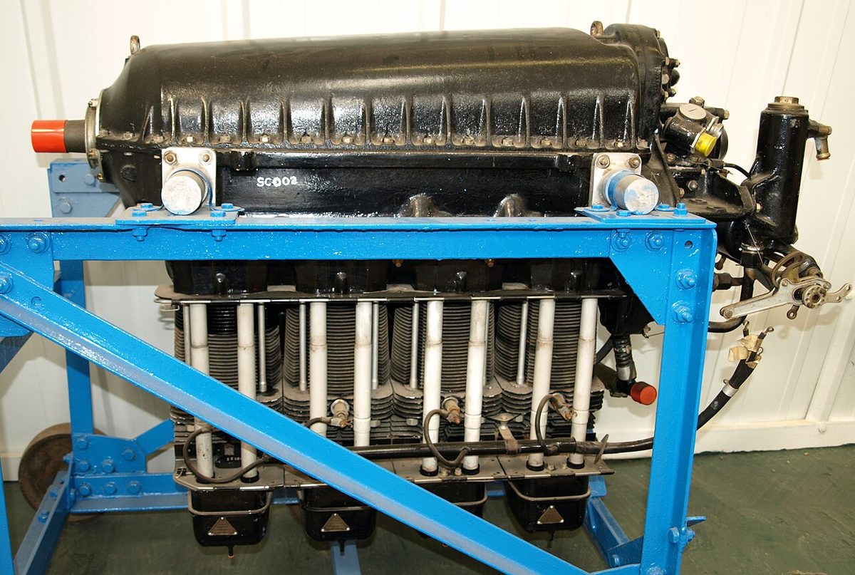
Every piston engine has the same moving parts. Each piston slides in a cylinder closed at the top by a cylinder head carrying the valves and spark plugs. A connecting rod joins the piston to a crank throw on the crankshaft, which turns the reciprocating motion into rotation and drives the propeller. A camshaft, geared to the crankshaft, opens the inlet and exhaust valves through tappets, pushrods and rocker arms. The crankcase holds the whole assembly and the oil that lubricates it.
The cylinders can be arranged in several ways:
- In-line: the cylinders in a single row, upright or inverted (hanging below the crankshaft), giving a narrow engine with a small frontal area.
- V: two rows of in-line cylinders set at an angle to each other on a common crankshaft.
- Horizontally opposed: two rows lying flat on opposite sides of the crankshaft. This flat, compact engine is the usual powerplant of light aeroplanes.
- Radial: cylinders arranged like the spokes of a wheel around a central crankcase, in one or more rows.
In radial and inverted engines oil can drain past the piston rings into the lowest cylinders while the engine stands. Oil is incompressible, so a cylinder full of it can be damaged on its compression stroke, a condition called hydraulic lock. These engines are pulled through by hand on the propeller before start, with the magnetos off, to make sure no cylinder is locked.
The four-stroke cycle
The piston travels between two dead points where it stops and reverses. Top dead centre (TDC) is its highest point in the cylinder and bottom dead centre (BDC) its lowest; the distance between them is the stroke, and the volume it sweeps is the swept volume. The four-stroke, or Otto, cycle has four strokes of the piston:
- Induction: the inlet valve is open and the descending piston draws the fuel/air charge into the cylinder.
- Compression: both valves are closed and the rising piston compresses the charge. The spark plugs fire shortly before TDC.
- Power: the burning charge raises the pressure sharply and drives the piston down. This power stroke is the only stroke that delivers work; as the gas expands and does work on the piston, its pressure and temperature fall.
- Exhaust: the exhaust valve is open and the rising piston pushes the burnt gas out.
The cycle takes two revolutions of the crankshaft and gives one power stroke per cylinder. The camshaft therefore turns at half crankshaft speed. Combustion is close to constant volume, because it takes place while the piston is near TDC in a closed cylinder, which is why the piston engine must withstand peak pressures of more than 1,000 psi and needs fuel resistant to detonation. The gas turbine, by contrast, burns its fuel at nearly constant pressure.
The charge takes time to burn, so the spark is timed before TDC so that peak pressure arrives some 8 to 10° after TDC, on a piston already moving down. The ignition systems article explains how the timing is set.
Valve timing: lead, lag and overlap
Near TDC and BDC the crankshaft turns through a large angle while the piston hardly moves and the cylinder volume barely changes. This region is the ineffective crank angle, and valve timing is arranged to use it. The valves do not open and close exactly at the dead points:
- Valve lead is the opening of a valve before its dead point. The exhaust valve opens well before BDC, near the end of the power stroke, so that the remaining pressure starts the exhaust gas flowing out. The inlet valve opens before TDC.
- Valve lag is the closing of a valve after its dead point. The inlet valve closes after BDC, so that the momentum of the incoming charge keeps filling the cylinder as the piston starts to rise. The exhaust valve closes after TDC.
- Valve overlap is the period around TDC, at the end of exhaust and the start of induction, when both valves are open together. The outflowing exhaust helps draw the fresh charge in and sweep out the burnt gas, improving scavenging and volumetric efficiency.
Valve timing is fixed by the shape and phasing of the cams. Measured in degrees of crankshaft rotation, lead, lag and overlap stay the same at every rpm.
Valve clearance is a small gap in the valve operating mechanism, set cold, that allows for expansion as the engine heats and makes sure each valve seats fully. Too much clearance must be taken up before the valve starts to open, so the valve opens late and closes early. Too little clearance makes the valve open early and close late; if the inlet valve is still open during compression, the charge is pushed back into the induction manifold, the "popping back" of a badly adjusted engine.
Exam tip: excessive valve clearance means late opening and early closing; insufficient clearance means early opening and late closing. Valve overlap does not change with engine speed.
Compression ratio and volumetric efficiency
The compression ratio is the total volume of the cylinder with the piston at BDC divided by the volume that remains with the piston at TDC. A higher ratio extracts more work from each charge: it gives better fuel utilisation (higher thermal efficiency) and a higher mean effective pressure, at the cost of higher working pressures and loads on the moving parts. It also brings the charge closer to detonation, so a high-compression engine must be run on the higher fuel grade it was designed for. A higher grade may be used where the flight manual permits it; a lower one never.
Volumetric efficiency compares the charge the cylinder actually takes in with the charge that would fill its swept volume at ambient pressure and temperature. In an engine without supercharging it is always below 100 per cent, because the induction system restricts the flow and the charge is heated on its way in. A partly closed throttle, hot induction air and high altitude all reduce the mass of charge per stroke; valve overlap and well-shaped induction passages improve it. A supercharged engine can exceed 100 per cent.
Horsepower and mean effective pressure
Horsepower is a rate of doing work: 1 hp is 33,000 ft-lb per minute, or 550 ft-lb per second, about 746 W. EASA material states engine power in kilowatts; FAA material and most flight manuals of American engines use horsepower.
The pressure in the cylinder varies throughout the cycle. The mean effective pressure (MEP) is the constant pressure that, acting on the piston through the power stroke, would do the same work as the real, varying pressure over the whole cycle. The power developed in the cylinders, the indicated horsepower, follows from it:
IHP = (P × L × A × N × K) ÷ 33,000
where P is the indicated MEP in psi, L the stroke in feet, A the piston area in square inches, N the number of power strokes per minute per cylinder (half the rpm in a four-stroke engine) and K the number of cylinders.
Part of the indicated power is absorbed by friction and by driving the engine's own pumps and accessories: this is friction horsepower. What reaches the propeller shaft is brake horsepower (BHP), so BHP = IHP − FHP, and their ratio is the mechanical efficiency. The MEP that corresponds to brake horsepower is the brake mean effective pressure, which is proportional to crankshaft torque. The propeller then turns brake horsepower into thrust horsepower; the ratio of the two is propeller efficiency.
Brake specific fuel consumption
Brake specific fuel consumption (BSFC) is the mass of fuel burned per hour for each unit of brake power, in kg/kW/h or, in FAA material, lb/hp/h. It measures how efficiently the engine turns fuel into shaft power: the lower the BSFC, the more efficient the engine.
For a piston engine the BSFC is roughly constant over the cruise power range, so fuel flow is roughly proportional to the power delivered. That is why a piston-propeller aeroplane achieves its maximum endurance at the speed for minimum power required. BSFC is lowest with the lean, best-economy mixture and rises with the rich mixtures used for maximum power and for cooling at high power, as explained in mixture control.
Compression-ignition engines
A compression-ignition engine compresses air alone, at a much higher compression ratio, until it is hot enough to ignite fuel injected directly into the cylinder. It needs no spark plugs and no carburettor, and power is controlled by the quantity of fuel injected rather than by throttling the air. Herbert Akroyd Stuart patented a compression-ignition oil engine in 1890 to 1891, ahead of Rudolf Diesel's patent of 1892, but such engines became known universally as diesels. The rest of this article, and the related articles, describe the spark-ignition engine that runs on AVGAS.
Cooling and cylinder head temperature
Much of the heat released by the fuel is not turned into work and must be carried away. Most aircraft piston engines are air-cooled. Their cylinders and heads are cast with deep, thin fins that greatly increase the area from which heat passes to the air, and baffles inside the cowling force the cooling air through the fins. The oil is an important coolant too, carrying heat away from pistons and bearings that the airflow cannot reach.
Cooling depends on airflow, so it is weakest at high power and low airspeed, as in a long climb on a hot day. Overheating can cause structural failure of engine parts, breakdown of the oil, and abnormal combustion: detonation and pre-ignition. The cylinder head temperature (CHT) gauge monitors it. When only one sensor is fitted it goes on the hottest cylinder, usually one of the rearmost, because the front cylinders meet the coolest, fastest air and the rear ones receive air already warmed.
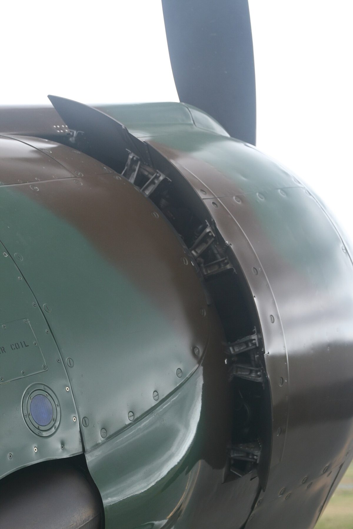
Cowl flaps are hinged doors at the rear or bottom of the cowling that increase the exit area for the cooling air. They are opened for ground running, take-off and climb, closed or partly closed in the cruise as the CHT allows, and closed in a long, low-power descent. If the CHT approaches its limit in a climb, the pilot lowers the nose for more airspeed, enriches the mixture, opens the cowl flaps and, if necessary, reduces power.
Note: a normally aspirated engine loses power as air density falls; the FAA's rule of thumb is roughly 3 per cent of sea-level power for every 1,000 ft of density altitude. Supercharging and turbocharging restore it.
Shock cooling
Shock cooling is a rapid fall in engine temperature, most often when power is reduced to idle at the start of a fast descent from a long cruise. The high airflow continues to cool cylinders that are no longer producing much heat, and the thin fins, the heads and the barrels cool at different rates. The resulting thermal stress is believed to crack cylinder heads and exhaust valves over time.
The remedy is planning. The pilot starts the descent early, reduces power gradually, keeps some power on, limits the rate of descent and closes the cowl flaps, so that the CHT falls slowly. In a long glide, ATPL training texts recommend opening the throttle to a cruise setting at intervals of 500 to 1,000 ft. This keeps the engine warm, keeps the carburettor heat supply effective, and burns off the lead deposits that build up on spark plugs at low power.
Frequently asked questions
How many crankshaft revolutions does a four-stroke cycle take?
Two. The induction, compression, power and exhaust strokes each take half a revolution, so one complete cycle of a cylinder takes two full turns of the crankshaft and gives a single power stroke. The camshaft is therefore geared to turn at half crankshaft speed, opening each valve once per cycle, and each spark plug fires once every second revolution.
What is valve overlap and why is it used?
Valve overlap is the period around top dead centre, at the end of the exhaust stroke and the start of induction, when the exhaust and inlet valves are both open. The outflowing exhaust gas helps draw the fresh charge in, which improves scavenging and volumetric efficiency. Overlap is set by the camshaft profile, so measured in degrees of crankshaft rotation it stays the same at every rpm.
What is the difference between indicated and brake horsepower?
Indicated horsepower is the power the burning gas develops on the pistons, calculated from the indicated mean effective pressure. Some of it is used to overcome friction and to drive the engine's own pumps and accessories; that part is friction horsepower. What remains, delivered at the propeller shaft, is brake horsepower. The propeller then converts brake horsepower into thrust horsepower with an efficiency below 100 per cent.
Why is the cylinder head temperature sensor fitted to the rear cylinder?
The CHT gauge is meant to protect the hottest cylinder. In an air-cooled engine the front cylinders meet the cooling air first, while those at the back receive air already warmed and slowed by the cylinders ahead of them. When only one sensor is fitted it therefore goes on the cylinder expected to run hottest, which on a typical in-line or flat engine is one of the rearmost.
What is shock cooling in a piston engine?
Shock cooling is a rapid fall in cylinder temperature, typically when power is cut to idle at the start of a fast descent. The high airflow keeps cooling the hot cylinders while little heat is being produced, so heads, barrels and valves cool unevenly. The resulting thermal stress is believed to crack cylinder heads and valves over time. It is avoided by planning the descent early and reducing power gradually.
Test yourself on Piston Engine Principles
The v1prep banks cover this topic in Aircraft General Knowledge (021), with a worked explanation for every answer. EASA ATPL, PPL, IR and CPL, the FAA written tests and A320/B737 type ratings.
Start practising →Sources and further reading
- FAA Pilot's Handbook of Aeronautical Knowledge (FAA-H-8083-25C), Chapter 7, Aircraft Systems
- FAA Aviation Maintenance Technician Handbook, Powerplant (FAA-H-8083-32B), Chapter 1, Aircraft Engines
- FAA Airplane Flying Handbook (FAA-H-8083-3C)
- EASA Easy Access Rules for Aircrew (Part-FCL), AMC and GM with the theoretical knowledge syllabus (021, Powerplant)
Library articles are written for study and exam preparation. They do not replace your aircraft's approved documentation, your operator's procedures or the regulations themselves.