Area Navigation (RNAV)
Area navigation (RNAV) is a method of navigation that lets an aircraft fly any desired path within the coverage of ground- or space-based navigation aids, within the limits of self-contained aids, or with a combination of both, instead of flying from one radio beacon to the next.
Area navigation (RNAV) frees an aircraft from the network of ground beacons. Instead of flying to a VOR and then along a radial to the next one, it flies between waypoints, points defined by latitude and longitude, wherever the designer has placed them. An RNAV system computes the aircraft's position from whatever sensors it has, GNSS, DME, VOR or inertial, and gives steering along the path to the next waypoint. The FAA lists the gains as time and fuel savings, less dependence on radar vectors and on ATC altitude and speed assignments, and more efficient use of airspace.
The term now has two meanings. In general it is the method, whatever the equipment, and that is what "RNAV" means in a procedure title. Within performance-based navigation, "RNAV 1" or "RNAV 5" names a navigation specification with a stated lateral accuracy. This article deals with the method: the sensors, the waypoints and legs, the errors, and the modes pilots use.
- The RNAV concept: 2D, 3D and 4D
- Position sensors and hybrid navigation
- Waypoints: fly-by and fly-over
- Path terminators and RF legs
- Desired track, cross-track and along-track error
- Lateral and parallel offsets
- Navigator modes: OBS and SUSP
- Map shift and position errors
- B-RNAV and P-RNAV
- Frequently asked questions
The RNAV concept: 2D, 3D and 4D
RNAV systems are classed by the dimensions they manage:
| Type | Guidance | Typical function |
|---|---|---|
| 2D RNAV | Horizontal plane only | Lateral navigation (LNAV) |
| 3D RNAV | Adds the vertical plane | Vertical navigation (VNAV): descent paths, altitude constraints |
| 4D RNAV | Adds time | Required time of arrival (RTA) at a waypoint |
A modern airline flight management system (FMS) is a 4D system. The first RNAV computers were much simpler 2D devices working from a single VOR/DME. The pilot defined a phantom waypoint, also called a phantom station, by its bearing and distance from the station, and the computer presented course and distance to it as if a beacon stood there. Each phantom waypoint had to lie within the designated operational coverage of its VOR/DME. Unlike a VOR needle, which shows degrees off a radial, the RNAV course deviation was displayed in nautical miles.
Position sensors and hybrid navigation
The FAA describes an FMS as an integrated suite of sensors, receivers and computers coupled with a navigation database. It accepts GNSS, DME, VOR, localiser and inertial inputs, alone or in combination, and some systems detect and isolate a faulty input. Hybrid navigation exploits the strengths of each. An inertial reference system is smooth and accurate over minutes but drifts with time; radio and satellite positions do not drift but are noisier from moment to moment and can be lost. A Kalman filter blends the two, weighting each source by its expected error. On the ground radio updating is inhibited, so an FMS without GNSS relies on its inertial position there.
When signals are available the FMS normally updates from GNSS or DME/DME. Each DME range places the aircraft on a circle round the station, and two circles cross at two points, of which the system takes the one near its own estimate: a DME/DME fix. The fix is best when the position lines cross at a wide angle and poor when the two stations lie almost in line with the aircraft. The FAA notes that DME/DME updating depends on the system's logic and on the proximity, availability, geometry and signal masking of the DME stations. Coupled with one or more inertial reference units it is written DME/DME/IRU, or D/D/I, the combination that meets RNAV 1 on many SIDs and STARs where GNSS is not required (see DME).
VOR/DME updating is less accurate than GNSS or DME/DME, and the AIM states that it must not be used for approach procedures. Charts may restrict the sensors: a Lyon STAR box reads "RNAV 1, GNSS or DME/DME (IRU required)", while a Toulouse STAR is "RNAV 1, GNSS only".
Waypoints: fly-by and fly-over
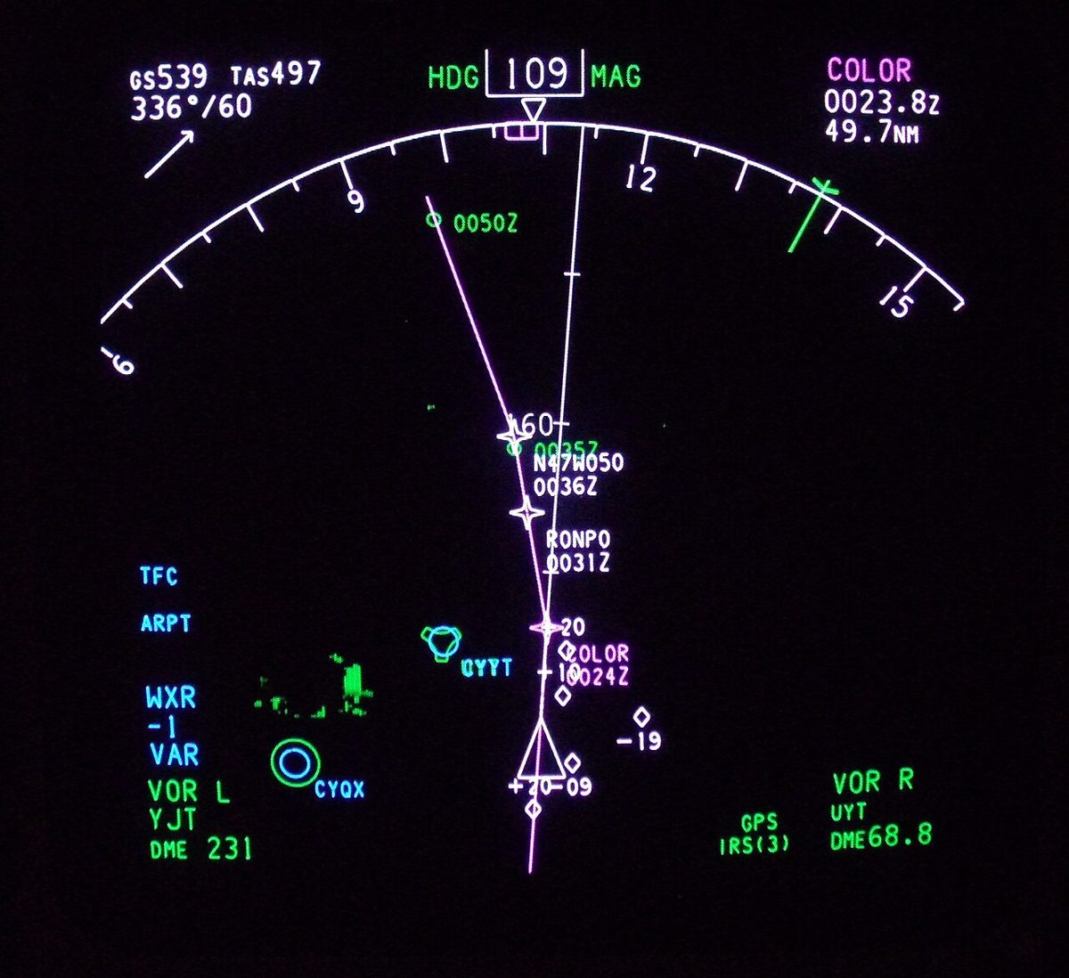
A waypoint is a predetermined geographical position defined by latitude and longitude, most often marking a change of direction, speed or altitude. It may be a named point in space or coincide with a navaid, intersection or fix. The coded procedure tells the system how to treat each one:
- A fly-by waypoint is turned before it is reached, so that the aircraft rolls out on the next leg. This turn anticipation is allowed for in the airspace and terrain clearances. Most waypoints are fly-by.
- A fly-over waypoint must be overflown before the turn begins. Charts draw it with a circle around the waypoint symbol. The missed approach waypoint is always fly-over, and a holding waypoint is coded as fly-over in the database.
The FAA also uses a computer navigation fix (CNF): a point, such as an unnamed DME fix or the end of a DME arc, needed by the RNAV system to build a procedure. CNFs carry five-letter identifiers in parentheses, increasingly beginning with CF, are unknown to ATC and must not be used for direct-to navigation, flight plans or radio communications with ATC. ICAO has not adopted the concept.
Path terminators and RF legs
Each leg of a coded procedure has a path terminator: a two-letter leg type describing the path flown and what ends it. The codes live in the database and are not normally shown on the chart, whose narrative describes the procedure. Common examples:
| Code | Leg | Chart narrative |
|---|---|---|
| TF | Track to fix | Direct ALPHA, then on course to BRAVO |
| DF | Direct to fix | Turn right direct BRAVO |
| CF | Course to fix | On course 150 to ALPHA |
| RF | Radius to fix | Constant-radius turn around a defined centre, ending at a fix |
| VA, VD, VM | Heading to an altitude, a DME distance, or manual termination | Climb heading 350 to 1500; fly heading 090, expect vectors |
A radius-to-fix (RF) leg gives a fixed curved path over the ground, whatever the wind, and lets designers route around terrain or noise-sensitive areas. It needs specific equipment and must be flown with the autopilot or flight director. RF capability is optional for RNP APCH and RNP 1 and mandatory for RNP AR and, in the FAA's definition, Advanced RNP, so an aircraft eligible for a procedure's specification may still be unable to fly its RF legs.
Because the database encodes the leg types, fly-over points and approach mode switching, the AIM requires an RNAV procedure to be retrieved by name from a current database, not entered as a series of waypoints.
Desired track, cross-track and along-track error
The desired track (DTK) is the planned track of the active leg between two waypoints. The system measures how far the aircraft is from it in two directions:
- Cross-track error (XTK), perpendicular to the desired track, is shown in nautical miles, left or right. On a GPS course deviation indicator full-scale deflection is ±5 NM en route (±2 NM on a WAAS receiver), ±1 NM in the terminal area and ±0.3 NM on final approach.
- Along-track error (ATE) is the position error along the track. The receiver displays along-track distance (ATD) to the next waypoint, which is not the same as a slant-range DME reading from a station.
Sensor geometry favours one or the other. With a VOR/DME ahead on the track, the DME measures the along-track position directly and that component is the more accurate; with the station abeam, the cross-track component is.
Lateral and parallel offsets
A parallel offset is an FMS function that flies a path parallel to the active route, a set distance left or right, for example to avoid weather or traffic with an ATC clearance; on the Airbus MCDU it is entered as a lateral revision. It is one of the functions the FAA requires for the Advanced RNP specification. A lateral offset is the general term for flying displaced from the centreline. In North Atlantic oceanic airspace the strategic lateral offset procedure (SLOP) lets crews fly on the centreline or 1 NM or 2 NM right of it, reducing the risk created by accurate navigation placing every aircraft on the same line and relieving wake turbulence.
Navigator modes: OBS and SUSP
A GPS navigator normally sequences automatically from one waypoint to the next. OBS mode, the non-sequencing mode, stops that: the receiver keeps the selected waypoint active and gives course and distance to it on a course the pilot sets, like a VOR. Most receiver manuals, the AIM notes, suggest it when vectored to final, to create an extended final approach course through the final approach waypoint, and pilots use it for holds and for procedure turns not coded in the database. It also stops the receiver sequencing unexpectedly while vectored or deviating for weather. The receiver must be back in automatic sequencing before the final approach fix.
At the missed approach waypoint the receiver stops sequencing on its own, shown on some units as SUSP (waypoint sequencing suspended), so the aircraft can land without the unit jumping to the missed approach. The AIM makes sequencing past the missed approach waypoint a pilot action: for a go-around the pilot starts the climb, does not turn before the waypoint, and then activates the missed approach on the receiver to obtain guidance to the missed approach holding fix.
Map shift and position errors
A map shift is a disagreement between the FMS position and the real one, so that the route and aircraft symbol on the navigation display are displaced. Boeing warns that an undetected cross-track shift can lead the aircraft along a track offset from the intended one, and an along-track shift can make it climb or descend early or late, compromising terrain or traffic separation. Causes include inertial drift without radio updating, database errors, a wrong runway or procedure selection and, increasingly, GNSS jamming and spoofing, which the AIM lists alongside unreliable terrain warnings and erroneous clocks. The defence is to cross-check the map with raw data from ILS, VOR, DME or ADF and to treat the FMS position as suspect when they disagree (see GNSS).

B-RNAV and P-RNAV
Europe introduced RNAV through two standards, still found in exam questions:
| Standard | Accuracy (95%) | Use | PBN equivalent |
|---|---|---|---|
| Basic RNAV (B-RNAV) | 5 NM | En-route airspace; described as RNP 5 | RNAV 5 |
| Precision RNAV (P-RNAV) | 1 NM | Terminal procedures, SIDs and STARs | RNAV 1 |
Both limits are total system error, the combination of path definition, flight technical and navigation system errors. B-RNAV could be met with VOR/DME, DME/DME, inertial or GNSS inputs; P-RNAV with DME/DME or GNSS, and with VOR/DME under conditions. AIP France still publishes terminal procedures marked "RNAV 1 and P-RNAV", protected for DME/DME and GNSS and usable with either approval, except by P-RNAV aircraft relying on VOR/DME alone. A crew without the required RNAV capability follows the published conventional procedure where one exists, or reports "Non RNAV terminal area" to obtain radar guidance.

Frequently asked questions
What is the difference between a fly-by and a fly-over waypoint?
At a fly-by waypoint the RNAV system starts the turn before reaching the waypoint so that the aircraft rolls out on the next leg, which is called turn anticipation. At a fly-over waypoint the aircraft must pass over the point before it starts turning. Fly-by is the default; fly-over is used where the procedure needs the fix itself to be crossed, and charts show it with a circle around the waypoint symbol. A missed approach waypoint is always fly-over.
What is DME/DME updating?
DME/DME updating is the method a flight management system uses to fix its position from the ranges to two or more DME stations, each range giving a circular position line. Combined with inertial reference units, as DME/DME/IRU, it meets RNAV 1 on many SIDs and STARs. Its quality depends on how many stations are in range, where they lie relative to the aircraft and whether their signals are masked by terrain.
What does OBS mode do on a GPS navigator?
OBS mode, the non-sequencing mode, stops the receiver moving automatically to the next waypoint and lets the pilot set a course to or from the active waypoint, as with a VOR. It is used for holding, for procedure turns not coded in the database and for intercepting an extended final approach course when vectored. The pilot returns the receiver to automatic sequencing before the final approach fix.
What were B-RNAV and P-RNAV?
They were European RNAV standards. Basic RNAV (B-RNAV) required a lateral accuracy of 5 NM for 95% of the flight time on en-route airspace and was described as RNP 5. Precision RNAV (P-RNAV) required 1 NM for 95% of the time on terminal procedures. Under performance-based navigation they correspond to the RNAV 5 and RNAV 1 specifications, and some charts still carry the mention RNAV 1 and P-RNAV.
What is a map shift?
A map shift is a difference between the position the flight management system believes and the real one, so that the route and the aircraft symbol on the navigation display are displaced from reality. An undetected cross-track shift makes the aircraft fly a track offset from the intended one; an along-track shift makes it start turns, climbs or descents early or late. Both can compromise terrain and traffic separation, so crews cross-check with raw data.
Test yourself on Area Navigation (RNAV)
The v1prep banks cover this topic in General and Radio Navigation (061/062), with a worked explanation for every answer. EASA ATPL, PPL, IR and CPL, the FAA written tests and A320/B737 type ratings.
Start practising →Sources and further reading
- FAA Aeronautical Information Manual, Chapter 1 Section 2 (1-2-1 RNAV waypoints and leg types, 1-2-3 RNAV on conventional procedures, 1-2-4 jamming and spoofing)
- FAA Aeronautical Information Manual, Chapter 1 Section 1 (1-1-17 GPS, waypoints, computer navigation fixes, non-sequencing mode)
- FAA Aeronautical Information Manual, Chapter 5 Section 4 (RNAV approach waypoints and RNP sensors)
- AIP France, ENR 1.5, Holding, Approach and Departure Procedures (RNAV 1 and P-RNAV terminal procedures)
- FAA Instrument Flying Handbook (FAA-H-8083-15B), Chapter 9, Navigation Systems
- FAA Instrument Procedures Handbook (FAA-H-8083-16B)
Library articles are written for study and exam preparation. They do not replace your aircraft's approved documentation, your operator's procedures or the regulations themselves.